
ChannelVessel Intelligent Equipment Co., Ltd. Contact Us
CUSTOM REACTOR VESSELS

Custom Reactor Vessels Engineered Around Your Process

From atmospheric and vacuum operation to pressure reactions, heating, cooling and agitation, we design and manufacture reactor vessels around the actual process conditions—not a standard tank configuration.
50–50,000 L+ Custom Volume
Vacuum to Pressure Process-Specific Design
−20°C to 300°C Typical Temperature Range
304 / 316L / CS / Alloy Material Options
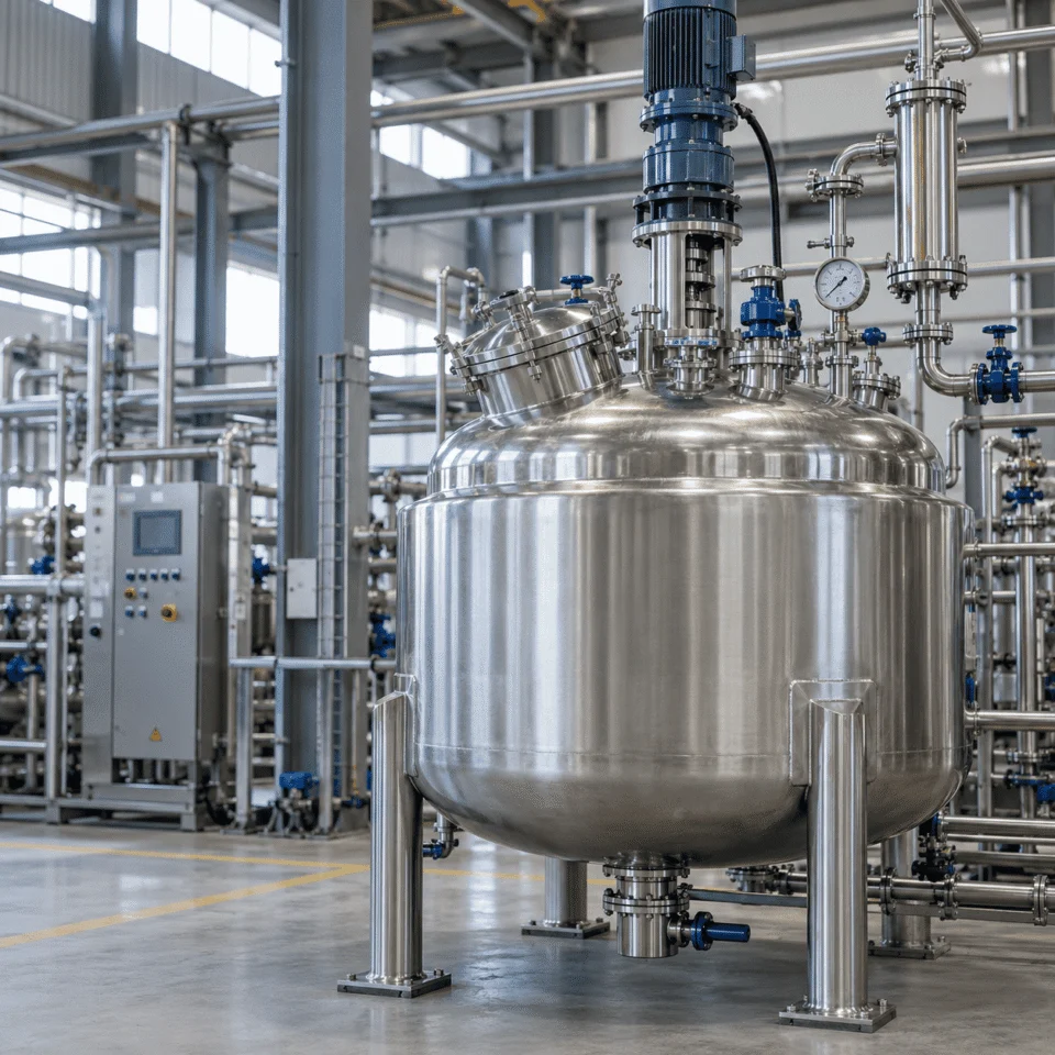
Custom stainless steel reactor vessel
ENGINEERED TO PROCESS Pressure · Heat Transfer · Mixing
PROCESS DEFINITION

A Reactor Is More Than a Mixing Tank

Both vessels can mix materials, but a reactor must also manage the conditions created by the reaction itself.

That changes the way the vessel, agitator, heat-transfer system, seals and safety provisions are engineered.

MIXING TANK

Primarily built to move and combine materials

B
Blending

Combine compatible liquids into a more uniform mixture.

D
Dissolving

Promote contact between soluble solids and the liquid phase.

S
Suspension

Keep solids distributed through the working volume.

H
Homogenization

Reduce concentration differences throughout the vessel.

T
Basic Temperature Control

Heating or cooling may support the mixing process.

REACTOR VESSEL

Engineered around what happens during the process

P
Reaction Pressure

Internal pressure can become a primary mechanical design condition.

V
Vacuum Operation

External-pressure stability must be reviewed separately from positive pressure.

Q
Reaction Heat

Heating and cooling duty must match the actual thermal load of the process.

G
Gas & Vapor Handling

Vent, reflux, condensation and vapor disengagement may become part of the design.

C
Containment & Control

Seals, relief devices and instrumentation must work with the process envelope.

WHY THIS MATTERS
Once the process introduces pressure, vacuum, reaction heat or vapor generation, vessel selection becomes a reactor-engineering problem.

The reactor must be reviewed as one system: vessel shell, mixing, heat transfer, sealing, instrumentation and safety provisions.

Pressure Vacuum Reaction Heat Vapor Handling
ENGINEERING INPUTS

From Process Conditions to Reactor Design

Changing one process condition can change several parts of the reactor at the same time.

The vessel should be configured from the process outward—mixing, heat transfer, pressure boundary, materials and maintainability all respond to what happens inside the reactor.

PROCESS CONDITION
DESIGN RESPONSE
High Viscosity

Higher resistance to flow changes mixing and thermal behavior.

Agitator geometry Motor torque Mixing speed Shaft design Heat-transfer performance
Solids in Liquid

Suspension duty changes how the impeller and vessel bottom should work together.

Impeller selection Agitator position Suspension velocity Bottom geometry Discharge arrangement
Exothermic Reaction

Reaction heat can make cooling duty one of the primary design inputs.

Cooling duty Jacket configuration Heat-transfer area Utility flow Temperature-control strategy
Vacuum Operation

External pressure creates a different mechanical design problem from internal pressure.

External-pressure design Shell stability Stiffening requirements Seal selection Nozzle & attachment design
Corrosive Media

Material compatibility must be reviewed together with temperature and concentration.

Wetted material Corrosion allowance Surface treatment Gasket selection Internal components
Frequent Batch Changes

Changeover frequency affects cleanability, access and internal geometry.

Drainability Cleaning access Internal geometry Dead-leg control Manway arrangement
ENGINEERING PRINCIPLE

A reactor should not be selected by capacity alone. Volume, pressure, temperature, chemistry, mixing and heat transfer must be reviewed together.

REACTOR CONFIGURATIONS

Choose the Reactor Configuration Around the Process Duty

The vessel type should follow the process requirement—not the other way around.

Heating and cooling, agitation, pressure, vacuum, material compatibility and project-specific geometry can all change the final reactor configuration.

Custom reactor vessel
REACTOR VESSEL Process-Driven Configuration
HEAT TRANSFER

Jacketed Reactors

For reactions requiring controlled heating or cooling through an external heat-transfer surface.

Steam Hot Water Thermal Oil
Explore Jacketed Reactors →
MIXING DUTY

Agitated Reactors

Configured around blending, suspension, dispersion, dissolution and reaction-uniformity requirements.

Anchor Turbine Custom Impeller
View Mixing Systems →
MATERIAL

Stainless Steel Reactors

304, 304L, 316 and 316L configurations for corrosion-resistant and clean-process applications.

304 / 304L 316 / 316L Polished Finish
Explore Stainless Steel Reactors →
PRESSURE

High-Pressure Reactors

For elevated-pressure reactions where vessel size, temperature, agitation and sealing must be reviewed together.

Pressure Service Seal Review Relief Design
Explore High-Pressure Vessels →
VACUUM

Vacuum Reactors

For reduced-pressure processing, evaporation, degassing, solvent handling and other vacuum duties.

Full Vacuum Shell Stability Seal Selection
Explore Vacuum Vessels →
PROJECT-SPECIFIC

Custom Process Reactors

Built from process data, equipment specifications, customer drawings or project-specific engineering requirements.

Custom Geometry Special Alloy Drawing-Based
Explore Custom Vessels →
CONFIGURATION PRINCIPLE A reactor can combine several of these categories at once.

A stainless-steel reactor may also be jacketed, agitated, designed for vacuum and engineered for pressure service. These are design attributes, not mutually exclusive product boxes.

MIXING ENGINEERING

Mixing Is an Engineering Input

The agitator must match what happens inside the reactor—not simply a target RPM.

Viscosity, solids, shear, heat transfer and reaction behavior can all change the impeller geometry, shaft arrangement, motor torque and operating speed.

Reactor vessel mixing system
SELECTION RULE Start with the process objective, then define the agitator.

Impeller type, diameter, shaft design, speed and drive power should be reviewed as one mixing system.

PROCESS INPUT WHAT IT CHANGES
A
Viscosity

Higher viscosity increases resistance to circulation and can shift the design toward lower-speed, higher-torque mixing.

Impeller geometry Torque Motor sizing Speed range
B
Solids Content

Particles must remain suspended without creating unnecessary settling zones or excessive local shear.

Impeller position Number of stages Bottom geometry Suspension duty
C
Required Shear

Some reactions need gentle circulation, while dispersion and emulsification may require concentrated high shear.

Impeller family Tip speed Energy input Product quality
D
Heat Transfer

Wall renewal and bulk circulation influence how effectively heat moves between the product and jacket or coil.

Wall movement Circulation pattern Jacket performance Heating / cooling time
E
Mixing Time & Reaction Uniformity

The process target determines how quickly concentration and temperature differences must be reduced.

Flow pattern Power input Circulation rate Scale-up approach
COMMON AGITATOR DIRECTIONS Different mixing objectives point toward different impeller families.
Propeller

Lower-viscosity circulation

Turbine

General mixing and dispersion

Paddle

Moderate low-speed mixing

Anchor

Higher-viscosity products

Helical Ribbon

Demanding bulk circulation

High-Shear

Dispersion and emulsification

WHY RPM ALONE IS NOT ENOUGH

Two reactors running at the same RPM can produce completely different mixing performance because vessel diameter, impeller diameter, viscosity, power input and flow pattern are different.

HEAT TRANSFER

Heating & Cooling Must Match the Process Duty

Selecting a jacket is not simply choosing whether the reactor needs heating or cooling.

Required heating or cooling time, process viscosity, utility temperature, agitation and available heat-transfer area must be reviewed together.

PROCESS DUTY What must the reactor achieve?
Heat Load How much energy must be added or removed?
Time Target How quickly must the batch heat or cool?
Utility Conditions What temperature, pressure and flow are available?
Product Behavior How do viscosity and agitation affect wall heat transfer?
HEAT-TRANSFER CONFIGURATION Choose the structure that fits the duty and utility side.
Configuration is project-specific
GENERAL DUTY

Conventional Jacket

A general-purpose external jacket for many heating and cooling applications where a full outer heat-transfer zone is appropriate.

Typical fit General batch heating & cooling
COMPACT SURFACE

Dimple Jacket

A compact external heat-transfer surface that can promote utility-side turbulence while keeping the jacket profile relatively close to the vessel wall.

Typical fit Compact external heat transfer
HIGHER UTILITY DEMAND

Half-Pipe Jacket

Often selected where higher utility-side pressure, demanding thermal duty or stronger external jacket construction is required.

Typical fit Higher utility pressure or duty
ADDITIONAL AREA

Internal Coil

An internal coil can add heat-transfer area when the external jacket alone cannot provide the required thermal performance.

Typical fit Additional internal surface area
UTILITY OPTIONS The heat-transfer structure and utility must be evaluated together.

Steam, hot water, cooling water, chilled water, thermal oil and electric heating can all be considered according to the process and required temperature range.

SteamHeating
Hot WaterHeating
Cooling WaterCooling
Chilled WaterCooling
Thermal OilHigher-temperature service
ElectricDirect heating option
ENGINEERING CHECK
More jacket area does not automatically mean better temperature control.

Performance also depends on utility temperature, utility flow, product viscosity, agitation, fouling and the required heating or cooling time.

MATERIAL SELECTION

Material Selection Starts With the Process Fluid

The correct material is the one that matches chemistry, temperature, cleanliness and mechanical requirements.

A higher alloy grade is not automatically the better choice. Concentration, chlorides, cleaning chemicals, operating temperature and contamination requirements all affect the final selection.

START HERE What does the product contact?

Process chemistry defines the wetted-material requirement before the vessel grade is selected.

CHEMISTRY Corrosion behavior

Acids, alkalis, chlorides, solvents and concentration all matter.

→
TEMPERATURE Service severity

Material compatibility can change significantly as temperature increases.

→
CLEANLINESS Contamination control

Food, pharma and sanitary duties may require cleaner finishes and lower surface roughness.

→
MECHANICAL DUTY Pressure & fabrication

Strength, weldability and code requirements also influence the final material choice.

GENERAL INDUSTRIAL

Carbon Steel

Where it fits

Compatible chemical and industrial services where stainless steel is not required.

Review carefully

Corrosion allowance, coating or lining strategy may become important.

GENERAL STAINLESS

SS304 / 304L

Where it fits

General industrial, clean-process and many non-aggressive product-contact applications.

Review carefully

Chloride exposure and aggressive cleaning chemicals may limit suitability.

CORROSION RESISTANCE

SS316 / 316L

Where it fits

Processes requiring increased corrosion resistance or higher hygiene performance.

Review carefully

Media concentration, chlorides and temperature still need confirmation.

SPECIAL ALLOY

Titanium

Where it fits

Selected highly corrosive services where conventional stainless steels may not be suitable.

Review carefully

Process chemistry, fabrication route and project specification must be confirmed.

SPECIAL ALLOY

Hastelloy

Where it fits

Demanding chemical environments requiring stronger corrosion resistance than conventional stainless steel.

Review carefully

The exact alloy should follow the actual process chemistry and service condition.

SURFACE FINISH Surface roughness should match the cleanliness requirement.

Industrial chemical service and sanitary product-contact service do not need the same internal finish.

GENERAL SERVICE Industrial Finish

For standard chemical and industrial applications.

CLEAN PROCESS Ra ≤ 0.8 μm

Available for sanitary and clean-process product-contact surfaces.

HIGHER HYGIENE Ra ≤ 0.4 μm

Available for higher-polish or electropolished requirements.

MATERIAL PRINCIPLE
Higher alloy grade does not automatically mean better reactor design.

The right material should be selected from the actual process chemistry, temperature, pressure, hygiene requirement and project specification.

DESIGN ENVELOPE

Capacity, Pressure & Temperature Must Be Read Together

A reactor's size, pressure and temperature are not independent maximum ratings.

A small high-pressure reactor and a large industrial process reactor may both belong to the same product family, but they create very different mechanical design problems.

CAPACITY REFERENCE Typical project volumes
100 L Compact process reactor
500 L Small batch production
1,000 L Production scale
2,000 L Mid-size process duty
5,000 L Industrial batch reactor
10,000 L Large process vessel
20,000 L Large industrial duty
30,000 L Project-specific design
50,000 L+ Subject to project review
Other capacities can be manufactured according to project requirements.
PRESSURE From atmospheric and vacuum service to elevated pressure
Vacuum External-pressure design
General Pressure Service Project-specific vessel design
Up to ~10 MPa Selected high-pressure configurations
High-pressure capability depends on vessel size, material, temperature, geometry, agitation and the complete mechanical design.
TEMPERATURE Typical reference range
−20°C
+300°C
Cooling Service General Process High-Temperature Duty
Higher or lower temperatures require project-specific review of material properties, seals, gaskets, jacket conditions and allowable stress.
DESIGN RELATIONSHIP Capacity × Pressure × Temperature

Increasing one design variable can change shell thickness, head geometry, nozzle reinforcement, support loads, agitator loads and fabrication requirements.

WHY THE NUMBERS CANNOT BE COMBINED BLINDLY Two reactors can share a product name while requiring completely different engineering.
COMPACT HIGH-PRESSURE DUTY 50 L × High Pressure

Smaller diameter and lower volume can support a very different pressure design approach than a large production reactor.

Thicker pressure boundary Seal review Pressure-rated fittings
LARGE PROCESS DUTY 50,000 L × Industrial Service

Large diameter and vessel weight create different fabrication, support, transport and structural considerations.

Large shell diameter Support design Fabrication logistics
IMPORTANT
50,000 L, 10 MPa and 300°C should not be read as one combined maximum operating point.

Final capability depends on the exact combination of volume, pressure, temperature, material, geometry, agitation and applicable design requirements.

MECHANICAL DESIGN

Pressure, Vacuum & Temperature Form One Design Envelope

These conditions must be reviewed as one mechanical system—not as three separate specifications.

Internal pressure checks containment, vacuum checks shell stability, and temperature changes the way materials, seals, jackets and connected components behave.
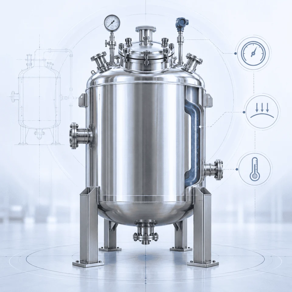
Reactor vessel pressure vacuum and temperature engineering
ONE MECHANICAL SYSTEM Shell · Heads · Nozzles · Supports · Seals · Jacket

The same reactor may experience different pressure and temperature conditions on the process side and utility side.

P
INTERNAL PRESSURE

Containment & Reinforcement

Positive internal pressure primarily drives the pressure-boundary and reinforcement checks.

Shell thickness Head design Nozzle reinforcement Flange rating Closure design Relief requirements
V
VACUUM / EXTERNAL PRESSURE

Stability Against Buckling

Vacuum creates a stability problem that cannot be judged from positive-pressure capability alone.

Vessel diameter Unsupported length Shell geometry Roundness Wall thickness Stiffening strategy
T
TEMPERATURE

Material & Thermal Behavior

Temperature affects material strength and how the vessel interacts with seals, gaskets and the heat-transfer system.

Allowable stress Thermal expansion Gaskets Mechanical seals Jacket interaction Cyclic operation
DESIGN INTERACTIONS Changing one condition can change how another condition must be reviewed.
Pressure + Temperature

Higher temperature can reduce allowable stress and change the required pressure-boundary thickness.

Vacuum + Diameter

Larger diameter can make external-pressure stability more demanding under the same vacuum condition.

Temperature + Jacket

The process shell and jacket may see different pressures and temperatures at the same time.

Agitation + Pressure Boundary

Drive, shaft, seal and nozzle loads must be considered together with the vessel design.

DESIGN PRINCIPLE
Positive-pressure capability does not automatically mean full-vacuum capability.

Internal pressure checks containment. Vacuum checks stability. Temperature affects both the material response and the connected process system.

DESIGN TRADE-OFFS

Reactor Design Is a Balance, Not a List of Options

More is not automatically better. Every design choice changes something else in the reactor system.

Good reactor design comes from balancing process performance, mechanical loads, heat transfer, maintainability, material compatibility and cost—not from maximizing a single specification.

COMMON ASSUMPTION More Agitation = Better Mixing

Increasing speed or power looks like the simplest way to improve mixing.

ENGINEERING REALITY Higher agitation also increases mechanical and process loads.
Shear Power consumption Shaft load Seal load Vibration Heat generation
COMMON ASSUMPTION More Jacket Area = Better Temperature Control

More surface area may help, but it is only one part of the thermal system.

ENGINEERING REALITY Heat-transfer performance depends on the whole duty.
Utility temperature Utility flow Process viscosity Agitation Fouling Time target
COMMON ASSUMPTION Thicker Shell = Complete Vacuum Solution

Wall thickness helps, but vacuum resistance is strongly affected by geometry and unsupported length.

ENGINEERING REALITY Vacuum design is a stability problem, not only a thickness problem.
Diameter Unsupported length Roundness Geometry Stiffening Fabrication tolerance
COMMON ASSUMPTION Higher Alloy Grade = Better Material

A more expensive alloy is not automatically the best choice for every process.

ENGINEERING REALITY Material must match the actual chemistry and service condition.
Process chemistry Concentration Temperature Chlorides Cleaning chemicals Contamination control
WHAT GOOD DESIGN DOES It balances competing requirements instead of maximizing one variable.
Process Reaction performance
Mechanical Pressure & loads
Thermal Heating & cooling
Material Compatibility
Operation Cleaning & maintenance
DESIGN PRINCIPLE
The best reactor is not the one with the highest specification in every category.

It is the reactor whose pressure boundary, mixing system, heat-transfer configuration, material and operating features work together for the actual process.

PROCESS CONNECTIONS

Configure the Reactor Around the Process Line

Nozzle locations, instruments, safety devices and connected equipment should follow the actual P&ID and operating sequence.

A reactor is not complete when the shell is finished. Feed, discharge, venting, sampling, measurement, relief and external process connections all have to work with the plant layout.
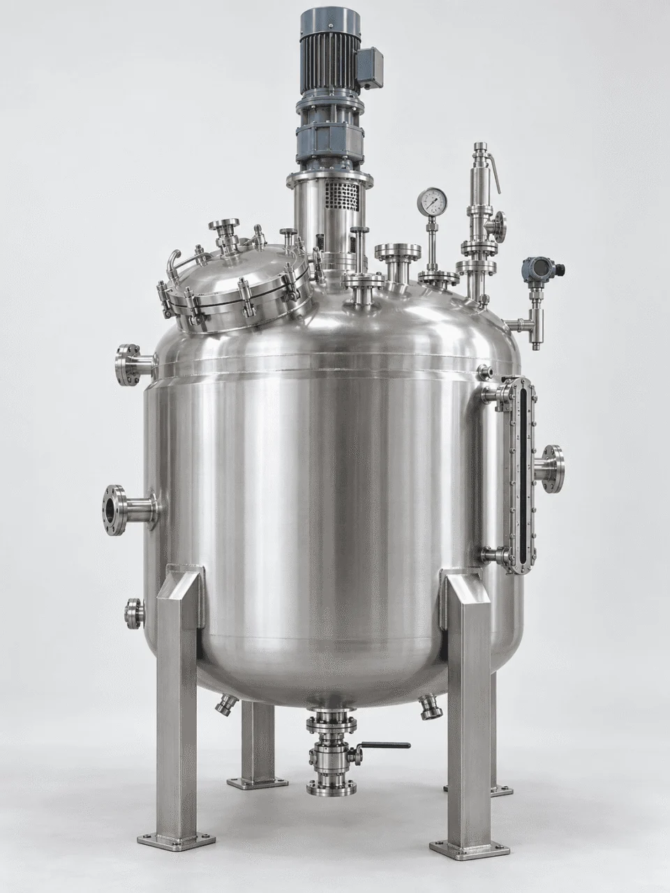
Reactor vessel nozzles instruments and process connections
PROCESS Process Connections
Feed inlet Bottom discharge Vent Vapor outlet Reflux connection Sampling port Drain CIP connection
ACCESS Operator & Inspection Access
Manway Handhole Sight glass Lighting port
INSTRUMENTATION Measurement & Control
Temperature sensor Pressure transmitter Pressure gauge Level instrument Load cells pH instrumentation Speed monitoring
SAFETY Protection & Relief
Safety valve Rupture disc Vacuum protection Emergency venting provisions
PROCESS EQUIPMENT Connected Equipment
Condenser Reflux system Filter Vacuum connection External circulation loop
LAYOUT PRINCIPLE
The final nozzle and instrument arrangement should follow the P&ID, process sequence and available installation space.

Two reactors with the same capacity may need completely different connection layouts because charging, sampling, cleaning, venting, reflux, maintenance access and surrounding piping are different.

OPERATION & MAINTENANCE

A Reactor Must Work After It Reaches the Plant

Mechanical design should also consider how operators will use, clean, inspect and maintain the equipment.

Two reactors can have similar process specifications but behave very differently in daily operation if access, drainage, maintenance clearance and serviceability are not considered early.

DESIGN FOR USE Think beyond fabrication.

The reactor has to fit into a real plant, with real operators, piping, maintenance tools and cleaning procedures.

ACCESS Can people reach it?
SERVICE Can components be removed?
CLEANING Can product residue be controlled?
INSPECTION Can internal condition be checked?
A
AGITATOR ACCESS

Can the agitator be removed for maintenance?

Motor, gearbox, shaft and impeller removal may require vertical lifting space, service clearance and access around the top head.

Top clearance Lifting route Drive access
B
SEAL MAINTENANCE

Is the mechanical seal accessible?

Seal replacement becomes difficult when surrounding piping, platforms or instruments block the drive-end service area.

Seal access Piping clearance Service space
C
DRAINABILITY

Can the vessel drain completely?

Bottom geometry, outlet elevation and valve arrangement can determine whether product remains trapped after discharge or cleaning.

Bottom geometry Outlet position Residual hold-up
D
MANWAY & INSPECTION

Can operators inspect internal surfaces safely?

Manway size, orientation and surrounding access affect inspection, cleaning and internal maintenance after installation.

Manway access Inspection visibility Internal reach
E
VALVES & INSTRUMENTS

Can instruments and valves be removed without major disassembly?

Transmitters, probes, gauges and bottom valves should remain serviceable after nearby piping and platforms are installed.

Probe removal Valve clearance Instrument access
F
CLEANING

Can the reactor be cleaned effectively?

Internal geometry, nozzles, dead zones and spray coverage should match the required cleaning method and product changeover frequency.

Spray coverage Dead zones Changeover
INSTALLATION CLEARANCE Maintenance space should be planned before the reactor reaches site.
TOP Drive removal

Allow vertical space for motor, gearbox, seal and shaft service.

SIDE Manway & instruments

Keep sufficient working space around access openings and removable probes.

BOTTOM Discharge & valve access

Provide clearance for valves, actuators, piping and maintenance tools.

AROUND Plant integration

Platforms, pipe racks and adjacent equipment should not block service routes.

OPERABILITY PRINCIPLE
A reactor that is difficult to clean, inspect or maintain can become a plant problem even when the process design is correct.

Operation and maintenance requirements should influence nozzle orientation, access, clearance, drainage and component arrangement before fabrication is finalized.

ENGINEERING & FABRICATION

From Process Data to a Finished Reactor

A custom reactor moves through a connected engineering and manufacturing sequence—not a collection of isolated fabrication steps.

Process conditions define the mechanical design, the mechanical design defines the fabrication basis, and inspection and testing verify that the finished vessel matches the agreed project requirements.

PROCESS REVIEW Define the real design inputs

Operating media, working volume, pressure, temperature, agitation, heat-transfer duty and material requirements are reviewed first.

Process fluid Pressure Temperature Mixing
MECHANICAL DESIGN Translate the process into vessel geometry

Shell, heads, jacket, nozzles, supports, agitator loads and applicable project requirements are brought into one design basis.

Shell Heads Nozzles Supports
MATERIAL & COMPONENTS Select what the process actually needs

Wetted material, jacket material, seals, gaskets, agitator components and process accessories are selected according to the agreed service conditions.

Material grade Seals Gaskets Accessories
FABRICATION Build from controlled manufacturing documents

Forming, fit-up, assembly and welding are completed against the approved equipment configuration and fabrication requirements.

Forming Fit-up Assembly Welding
WELDING & INSPECTION Verify critical fabrication quality

Visual inspection and any required NDT are defined according to the vessel design, project specification and agreed inspection scope.

VT PT / MT UT / RT Dimensional check
PRESSURE / LEAK TESTING Test the completed pressure boundary

Hydrostatic, pneumatic or leak testing is carried out according to the equipment specification and agreed test requirements.

Hydro test Leak test Functional check
FINAL DOCUMENTATION Close the project with the required records

Project documentation can be prepared according to the agreed scope, including drawings, material records, inspection records and test documentation.

Drawings Material records Inspection records Test records
PROJECT CONTROL Each stage should feed the next one with controlled information.

Changes to process data, material, pressure, temperature, nozzles or agitation should be reflected in the engineering and manufacturing basis before final fabrication proceeds.

Input Process data
→
Engineering Approved design basis
→
Manufacturing Fabrication documents
→
Verification Inspection & test records
APPLICATIONS & RFQ

Reactor Vessels for Different Process Industries

The same reactor platform can be configured very differently depending on the industry, product behavior, hygiene requirement and operating conditions.

Use the application links to explore industry-specific requirements, or send your process data so we can review the reactor configuration around your project.

REQUEST FOR QUOTATION

What Should You Send Us for a Reactor Vessel Quote?

The more process information we receive, the more accurately the reactor can be configured.

BASIC VESSEL DATA
Working volume Total volume if known Vessel orientation Installation location
PROCESS CONDITIONS
Process medium Composition Density Viscosity Solid content Corrosive components
PRESSURE & TEMPERATURE
Operating pressure Design pressure Vacuum requirement Operating temperature Design temperature
HEAT TRANSFER
Heating medium Cooling medium Heating time Cooling time Reaction heat load
AGITATION
Mixing purpose Mixing time Viscosity Solid suspension Shear requirement
MECHANICAL CONFIGURATION
Material Surface finish Nozzles Manway Instrumentation Seal preference
YOU CAN ALSO SEND
Equipment datasheet P&ID GA drawing Existing reactor drawing Process specification
REACTOR VESSEL FAQ

Questions Buyers Often Ask Before Finalizing a Reactor

The correct answer usually depends on the process conditions, not only the vessel capacity.

These questions cover the information, pressure conditions, jacket options, agitation, materials, drawings and accessories typically reviewed before a reactor configuration is finalized.

ENGINEERING FAQ Start with the process, then confirm the vessel.

Pressure, vacuum, temperature, mixing, heat transfer and material selection are connected decisions. If your project already has a datasheet or drawing, those documents can be used as the starting point for review.

Process Media & reaction duty
Mechanical Pressure & temperature
Thermal Heating & cooling
Mixing Viscosity & shear
What information is required to design a reactor vessel?

At minimum, working volume, process medium, pressure, temperature, material and basic mixing requirements are needed. Heat-transfer data, viscosity, solids content and drawings allow a more accurate configuration.

Can a reactor vessel operate under both pressure and vacuum?

Yes, when both operating conditions are included in the mechanical design. Positive-pressure capability alone does not automatically mean the reactor is suitable for full vacuum.

What jacket types are available?

Common options include conventional jackets, dimple jackets, half-pipe jackets and internal coils. The correct arrangement depends on heat-transfer duty, utility conditions and mechanical requirements.

How is the agitator selected?

Selection depends on viscosity, density, solids, shear requirement, vessel geometry, heat transfer and the actual mixing objective. RPM alone is not enough to define the mixing system.

What materials can be used?

Common materials include carbon steel, SS304/304L and SS316/316L. Titanium, Hastelloy and other project-specified materials can also be considered for demanding applications.

Can you manufacture a reactor from our drawings?

Yes. Reactors can be manufactured from customer drawings, datasheets and project specifications after technical review.

Can you supply instruments and process accessories?

Yes. Reactor configurations can include instrumentation, valves, safety devices, condensers, CIP connections, sampling systems and other project-specific components.

What sizes of reactor vessels can you manufacture?

Typical projects can range from small process reactors to large industrial vessels, with reference capacities extending from approximately 50 L to 50,000 L and above. Final capability depends on pressure, temperature, material and equipment configuration.

Scroll to Top
DRAWING & FILE REVIEW

Send Your Drawings

Upload your drawings, datasheets or existing specifications. Our engineering team will review the files and respond with technical feedback.

Engineering Review

Drawings, specifications and process requirements

Confidential File Handling

Project files are used only for technical review and quotation

Faster Technical Feedback

Clearer inputs help us respond more accurately and efficiently

DRAWING & FILE REVIEW

Send Your Drawings

Upload your drawings, datasheets or specifications. Our engineering team will review your files and provide technical feedback.

Contact Form Demo (#3)
Project Protected NDA available
12h Response
ASME / PED
AFTER SUBMISSION
01 Review
→
02 Confirm
→
03 Quote
TECHNICAL QUOTATION

Get a
Technical Quote

Tell us what you need. Our engineering team will review your requirements and respond within 12 hours.

Engineered for Your Application

From concept to certified manufacturing

Global Compliance

ASME, PED and other international standards

Expert Support

Direct access to our engineering team

TECHNICAL QUOTATION

Get a Technical Quote

Tell us what you need. Our engineering team will review your requirements and respond within 12 hours.

Contact Form Demo
Project Protected NDA available
12h Response
ASME / PED
AFTER SUBMISSION
01 Review
→
02 Confirm
→
03 Quote