
ChannelVessel Intelligent Equipment Co., Ltd. Contact Us
SHELL & TUBE HEAT EXCHANGERS

Custom Shell and Tube Heat Exchangers

ChannelVessel designs and manufactures custom shell and tube heat exchangers for heating, cooling, condensation and heat-recovery duties across industrial process systems.

Fixed tubesheet, U-tube and floating head configurations can be engineered around the actual service conditions, with carbon steel, stainless steel and project-specified material combinations available according to the application.

We do not size an exchanger from heat-transfer area alone. Each design is reviewed around heat duty, temperature program, fluid properties, allowable pressure drop, fouling tendency, corrosion conditions, cleaning method, thermal expansion, design pressure and design temperature.

Fixed Tubesheet U-Tube Floating Head
Shell and tube heat exchanger manufactured by ChannelVessel
DESIGN STARTS WITH THE PROCESS

What Defines the Exchanger

Heat Duty Required heating or cooling load
Temperature Program Hot- and cold-side inlet / outlet conditions
Allowable Pressure Drop Available ΔP on shell and tube sides
Fouling & Cleaning Deposit behavior and maintenance method
Design Conditions Pressure, temperature and material requirements
ENGINEERING SELECTION

Start With the Process, Not the Exchanger Type

The exchanger configuration should be the result of the process conditions — not the starting point.

Two shell-and-tube heat exchangers with similar heat-transfer area can require completely different internal arrangements because the fluids, operating pressures, fouling tendency, thermal expansion and cleaning requirements are different.

SELECTION PRINCIPLE Select the exchanger around the process.

Do not force the process into a preferred exchanger type.

PRESSURE

Which side operates at the higher pressure?

Placing a high-pressure stream on the tube side can often reduce the amount of material required to contain the pressure compared with designing a large-diameter shell for the same condition.

Pressure is a starting factor, not the only fluid-allocation rule.
FOULING

Which fluid is more likely to foul?

A fluid that leaves deposits may need direct access for mechanical cleaning. That requirement can influence whether it belongs inside straight tubes, whether the bundle must be removable and whether a U-tube arrangement is practical.

Fouling behavior can eliminate a configuration before thermal sizing begins.
CLEANING

What kind of cleaning access is actually required?

“Cleanable” is not one condition. Tube-side access, shell-side access, chemical cleaning, mechanical tube cleaning, bundle removal and access to the outside of the tubes are different maintenance requirements.

The maintenance method should be defined before the mechanical arrangement is locked.
EXPANSION

How different are the shell-side and tube-side temperatures?

The shell and tubes expand independently as their temperatures change. When differential movement becomes significant, the mechanical configuration must be able to accommodate it.

Thermal expansion can become a configuration decision, not a later calculation.
PRESSURE DROP

How much pressure drop is actually available?

Higher velocity can improve heat transfer, but the same change also consumes more pressure drop. A practical design has to balance heat-transfer performance, hydraulic limits and long-term operating behavior.

The target is a balanced exchanger — not maximum velocity or maximum surface area.
THEN SELECT THE CONFIGURATION
Fixed Tubesheet U-Tube Floating Head
CONFIGURATION SELECTION

Fixed Tubesheet, U-Tube or Floating Head?

There is no universally “best” shell-and-tube arrangement. Each configuration trades fabrication simplicity, cleaning access, thermal expansion capability and maintenance requirements differently.

FIXED

Fixed Tubesheet

Mechanically straightforward construction with the tubesheets fixed to the shell.

OFTEN CONSIDERED WHEN
  • The fluids are relatively clean
  • Shell-side mechanical cleaning is not a major requirement
  • Temperature differences can be managed within the mechanical design
  • A simpler construction is preferred
KEY DESIGN CHECK

Straight tubes can provide convenient tube-side cleaning access, but the tube bundle is normally not removable. Shell-side deposits may therefore require chemical cleaning or another maintenance method.

Differential thermal expansion still has to be checked rather than assumed acceptable.
U-TUBE

U-Tube

The tube bundle can accommodate thermal movement through the U-bend geometry.

OFTEN CONSIDERED WHEN
  • Differential thermal expansion is important
  • Shell-side access is required
  • A removable-bundle arrangement is desirable
  • The service is compatible with U-bend cleaning limitations
KEY DESIGN CHECK

In common removable-bundle U-tube configurations, shell-side access can be good, but mechanical cleaning through the U-bend is more difficult than cleaning a straight tube from end to end.

“Removable bundle” does not automatically mean “easy to clean everywhere.”
FLOATING

Floating Head

One end of the tube bundle is allowed to move relative to the shell.

OFTEN CONSIDERED WHEN
  • Differential thermal expansion is significant
  • Shell-side mechanical access is important
  • The bundle must be removable
  • Straight-tube cleaning access is required depending on the rear-head arrangement
KEY DESIGN CHECK

Floating-head exchangers can provide strong maintenance flexibility, but they contain more components and sealing interfaces than simpler arrangements.

The added maintenance access should solve a real process requirement rather than be specified automatically.
CONFIGURATION DECISION MATRIX

Compare the Design Consequences

Design QuestionFixed TubesheetU-TubeFloating Head
Differential expansionRequires evaluationStrong flexibilityStrong flexibility
Tube-side mechanical cleaningGood with suitable headLimited through U-bendGood depending on head
Shell-side mechanical accessLimitedGood with removable bundleGood
Bundle removalNormally noCommonly availableYes
Construction complexityLowerMediumHigher
Maintenance flexibilityLowerMediumHigher
MAINTENANCE CLEARANCE

Can You Actually Pull the Bundle Out at Site?

A drawing may show a removable bundle. The installation may not. Extraction space has to be reviewed together with piping, platforms, structural steel, walls and lifting access.

If the bundle requires several metres of pull space but the plant provides only a narrow service corridor, the exchanger may be technically removable and practically impossible to maintain.

Maintenance clearance is a design input, not an afterthought.
FLUID ALLOCATION

Which Fluid Should Go on the Tube Side?

Tube side or shell side is not decided by one rule. Pressure, corrosion, fouling, viscosity, phase change and allowable pressure drop have to be considered together.

TUBE SIDE

Often Favored When Containment or Cleaning Drives the Decision

Smaller tube diameters can make pressure containment more practical, and straight tubes can provide direct mechanical cleaning access when the channel arrangement allows it.

ALLOCATE BY SERVICE
SHELL SIDE

Often Favored When Distribution, Phase Change or Geometry Benefits

Shell-side flow can be useful where crossflow, vapor handling, condensation, boiling or a larger flow area better suits the process conditions.
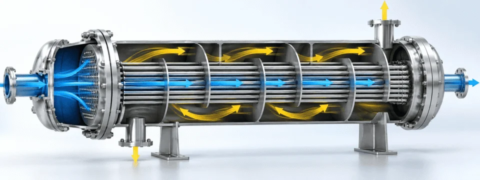
Shell and tube heat exchanger internal flow path showing tube-side and shell-side fluid allocation
HIGHER PRESSURE

High-pressure streams are frequently considered for the tube side.

The smaller tube diameter can make pressure containment more practical than pressurizing a much larger shell.

Useful starting principle — not an automatic rule.
CORROSION

A corrosive stream may be placed where expensive alloy use can be controlled.

When only one process stream requires a costly corrosion-resistant material, tube-side allocation can sometimes reduce the total amount of alloy required.

All wetted components still need to match the actual corrosion mechanism.
FOULING

Decide how deposits will be removed before deciding the flow path.

Straight tube-side passages can offer direct mechanical cleaning access. A heavily fouling stream placed where access is poor can turn a thermally successful exchanger into a maintenance problem.

Cleaning access can outweigh a simple thermal preference.
VISCOSITY

Viscosity changes the hydraulic and thermal picture.

It affects velocity, Reynolds number, pressure drop and heat-transfer behavior. Generic “put the viscous fluid here” rules can fail when the full operating conditions are ignored.

Evaluate viscosity together with available ΔP and target velocity.
CONDENSING / VAPORIZING SERVICE

Phase change introduces another design layer.

Condensation or boiling can change the preferred side because fluid distribution, drainage, vapor disengagement, pressure drop and orientation become part of the design problem.

Do not allocate by “hot side / cold side” convention alone.
THE REAL DESIGN TRADE-OFF

Velocity, Fouling and Pressure Drop Have to Be Balanced Together

More velocity is not always better. Less pressure drop is not always better. The exchanger has to reach the required duty without creating a hydraulic, fouling or mechanical penalty.

VELOCITY Flow speed changes both thermal and hydraulic behavior.
HEAT TRANSFER Higher velocity can improve the heat-transfer coefficient.
PRESSURE DROP The same increase in velocity also consumes more available ΔP.
TOO LOW

If Velocity Is Too Low

Weak surface shear can encourage deposit accumulation in some services. Poor distribution can also leave part of the exchanger surface underutilized.

Fouling tendency may increase Heat-transfer performance may weaken More area does not automatically solve the problem
ENGINEERING WINDOW

The Target Is a Balanced Operating Range

The objective is to establish a flow condition that delivers the required heat-transfer performance while staying within the process pressure-drop limit and avoiding unnecessary fouling, erosion or vibration risk.

Required duty is achieved Available ΔP is respected Velocity remains compatible with long-term operation
TOO HIGH

If Velocity Becomes Excessive

Pressure loss can become unacceptable. Depending on the fluid and exchanger geometry, high local velocities may also increase erosion risk or contribute to flow-induced vibration.

Pressure drop rises Erosion risk can increase Mechanical vibration concerns may appear
BIGGER IS NOT ALWAYS BETTER

More Heat-Transfer Area Can Reduce Velocity

Adding more tubes increases surface area. But if the same process flow is divided through substantially more parallel flow area, tube-side velocity can fall.

More Tubes More parallel flow area
Lower Velocity Same flow divided across more area
Potential Fouling Penalty Hydraulic conditions may worsen
Heat-transfer area is only one design variable.
SHELL-SIDE ENGINEERING

Baffle Design Changes More Than the Flow Direction

Baffles guide shell-side flow across the tube bundle, but they also change velocity, pressure drop, flow distribution, tube support and vibration behavior.

SHELL-SIDE FLOW PATH
Changing one baffle dimension changes several design variables at once.

Spacing, cut, leakage paths and unsupported tube length should be reviewed together.

BAFFLE SPACING

Spacing changes shell-side crossflow velocity.

Closer spacing can increase shell-side velocity and heat transfer, but it also increases pressure drop and changes tube support conditions.

BAFFLE CUT

The open area changes how fluid crosses the bundle.

Too much or too little window area can alter crossflow velocity, hydraulic resistance and the distribution of shell-side flow.

FLOW DISTRIBUTION

Real shell-side flow is not perfectly ideal.

Leakage paths, bypass streams, bundle clearances and local geometry affect how much fluid actually crosses the active tube field.

TUBE SUPPORT

Baffle geometry also affects vibration behavior.

Shell-side velocity, unsupported tube span and local flow pattern should be reviewed together when flow-induced vibration is a concern.

DESIGN RELATIONSHIP
Baffle Geometry Spacing + cut + clearances
Shell-Side Velocity Crossflow intensity changes
Heat Transfer Coefficient responds to flow
Pressure Drop Hydraulic cost increases
Tube Support Vibration risk is affected
DIFFERENTIAL EXPANSION

Thermal Expansion Can Decide the Mechanical Configuration

The shell and tube bundle may operate at different metal temperatures and may not expand by the same amount. That relative movement has to be considered before the exchanger configuration is finalized.

RELATIVE THERMAL MOVEMENT
SHELL ΔL shell
TUBES ΔL tubes
DIFFERENTIAL MOVEMENT ΔL shell ≠ ΔL tubes

If relative movement is restrained, thermal stresses can develop in the tubes, tubesheets, shell and associated joints.

TEMPERATURE DIFFERENCE ALONE IS NOT ENOUGH

What actually influences the expansion check?

Metal Temperature

The shell and tubes respond to the temperature of the metal itself, not only the fluid inlet temperature.

Material

Different materials can have different thermal expansion characteristics.

Effective Length

Longer effective lengths can create greater total dimensional change for the same temperature shift.

Operating Modes

Normal operation is only one condition the exchanger may experience.

Start-Up & Shutdown

Transient conditions can create a different temperature relationship than steady-state operation.

Mechanical Restraint

The way the shell and bundle are restrained changes how thermal movement turns into stress.

MECHANICAL RESPONSE

Different configurations handle relative movement differently.

FIXED TUBESHEET Movement is more restrained.

Differential expansion has to be checked carefully because the tubesheets are fixed to the shell.

EXPANSION JOINT Shell flexibility can be introduced.

Depending on the service and mechanical design, an expansion joint may be considered to accommodate shell-side movement.

U-TUBE The U-bend accommodates tube movement.

Individual tubes can flex as the bundle expands and contracts, which can reduce restraint from differential expansion.

FLOATING HEAD The bundle can move relative to the shell.

The floating end allows relative movement while also supporting a removable-bundle maintenance strategy.

An exchanger that is acceptable at steady-state operation may experience a different thermal condition during start-up, shutdown or upset conditions.

FROM DUTY TO FABRICATED EQUIPMENT

Thermal Design ≠ Mechanical Design

Meeting the heat duty is only the beginning. A practical shell-and-tube heat exchanger has to move from thermal performance into hydraulic, maintenance and mechanical decisions before it is ready to manufacture.

HEAT DUTY How much heat must move?

Define the required heating, cooling, condensing or heat-recovery load.

TEMPERATURE PROGRAM What temperatures must be achieved?

Hot- and cold-side inlet / outlet conditions define the thermal target.

AREA How much effective surface is required?

Area follows from duty, temperature driving force, heat-transfer behavior and fouling assumptions.

VELOCITY What flow condition does the geometry create?

Tube count, passes and flow area directly change velocity.

PRESSURE DROP Can the process tolerate the hydraulic cost?

Thermal improvement is not useful if the system cannot supply the required ΔP.

FOULING How will performance change after months of operation?

Long-term cleanliness and maintenance access belong in the design basis.

VIBRATION Is the selected flow mechanically acceptable?

Tube support and shell-side flow conditions need to be reviewed together.

THERMAL EXPANSION Can the shell and bundle move safely?

Differential movement may influence the exchanger configuration itself.

MECHANICAL DESIGN Now the pressure-retaining equipment can be finalized.

Shell, tubesheets, channels, nozzles, supports, joints and other components follow the complete design conditions.
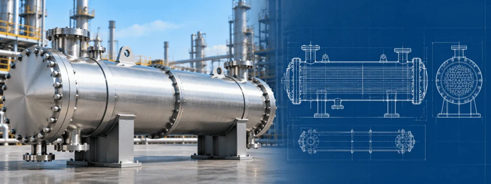
Shell and tube heat exchanger with engineering drawing
THERMAL DESIGN ANSWERS

Can the required duty be achieved?

Heat load Required duty
Temperature driving force Available thermal potential
Surface area Required heat-transfer area
Flow arrangement Shell / tube passes and temperature profile
Pressure drop Hydraulic response of the selected geometry
NOT FINISHED
MECHANICAL DESIGN STILL ASKS

Can the equipment survive and be maintained?

Pressure containment Shell, heads, tubesheets and channels
Thermal expansion Relative shell / tube movement
Tube support Unsupported span and vibration control
Connections & loads Nozzles, supports and plant interfaces
Inspection & fabrication Joint design, access and manufacturing requirements
ENGINEERING CHECK A heat exchanger can satisfy the calculated duty on paper and still be poor equipment in service.

Thermal performance, pressure drop, fouling, cleaning, vibration, expansion and mechanical construction have to work as one design.

BUILT AROUND THE SERVICE

Materials and Construction Options

The same material does not need to be used everywhere. Shell, tubes, tubesheet, channels and internal components can be selected around the fluid contacting each part, corrosion mechanism, pressure, temperature and project specification.

COMPONENT-LEVEL MATERIAL SELECTION

Different parts of the exchanger can solve different material problems.

SHELL Pressure boundary around the tube bundle
Carbon Steel Stainless Steel Project-Specified Alloy
HEAT-TRANSFER TUBES Primary heat-transfer surface
SS304 / 304L SS316 / 316L Duplex Stainless Steel Titanium Project-Specified Tube Material
TUBESHEET Interface between shell side and tube side
Carbon Steel Stainless Steel Solid Alloy Clad / Overlay Construction
CHANNELS & COVERS Tube-side pressure boundary and maintenance access
Selected by pressure Selected by corrosion Selected by access requirement
BAFFLES & INTERNALS Shell-side flow control and tube support
Fluid compatibility Temperature Mechanical requirements
TUBE LAYOUT IS ALSO A DESIGN VARIABLE

Fitting more tubes into the shell is not the only objective.

Tube arrangement affects shell-side flow, heat-transfer density, pressure drop and the ability to clean between tubes. The preferred pattern depends on what the service needs.

Triangular / Rotated Triangular

Can provide compact tube density and strong shell-side crossflow characteristics.

Square / Rotated Square

Can provide more direct cleaning lanes when shell-side mechanical cleaning matters.

TUBE-TO-TUBESHEET JOINT

The joint method should match the service, not habit.

Expanded Joint

Mechanical expansion can be used where the service and leakage requirements allow it.

Welded Joint

Welding can be considered where pressure, leakage risk or service conditions justify it.

Welded + Expanded

Combined construction can be selected where both sealing and mechanical requirements need to be addressed.

Project-Specific Joint

Cyclic service, corrosion, code requirements and customer specifications can change the preferred joint detail.

ORIENTATION

Horizontal or vertical installation can be engineered around the process.

Orientation can influence drainage, venting, phase behavior, plant layout and maintenance access.

CONNECTIONS

Nozzles and flanges should fit the plant — not a fixed catalog drawing.

Nozzle size, flange standard, orientation and instrument connections can be integrated with the project piping layout.

APPLICATIONS

One Mechanical Platform, Very Different Process Duties

Shell-and-tube construction can be adapted across many industries, but the exchanger should follow the actual fluid, phase behavior, pressure, fouling tendency and maintenance requirement of each service.

Chemical industry process equipment
CHEMICAL PROCESSING

Chemical Industry

Process liquid heating Process cooling Solvent service Reactor temperature control Condensation
Design focus

Corrosion, fouling and cleaning can dominate material selection, fluid allocation and exchanger configuration.

Petrochemical process equipment
PETROCHEMICAL PROCESSING

Petrochemical Industry

Hydrocarbon heating Hydrocarbon cooling Feed / effluent recovery Condensing service Utility exchangers
Design focus

Pressure, temperature, allowable ΔP and heat-recovery targets can strongly influence area, passes and mechanical design.
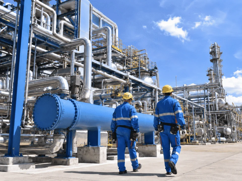
Oil and gas process equipment
OIL & GAS

Oil & Gas

Process cooling Gas conditioning Liquid conditioning Oil cooling Heat recovery
Design focus

Pressure containment, phase behavior and field maintenance constraints can drive fluid allocation and configuration.

Pharmaceutical stainless steel process equipment
PHARMACEUTICAL PROCESSING

Pharmaceutical Industry

Utility heating Utility cooling Water systems Controlled process duties
Design focus

Material selection, cleanability, surface requirements and project documentation may become more specific.

Food and beverage stainless steel process equipment
FOOD & BEVERAGE

Food & Beverage

Water heating Utility cooling Process temperature control CIP-related utility duties
Design focus

The construction should match whether the exchanger is used for utility service or product-contact service.
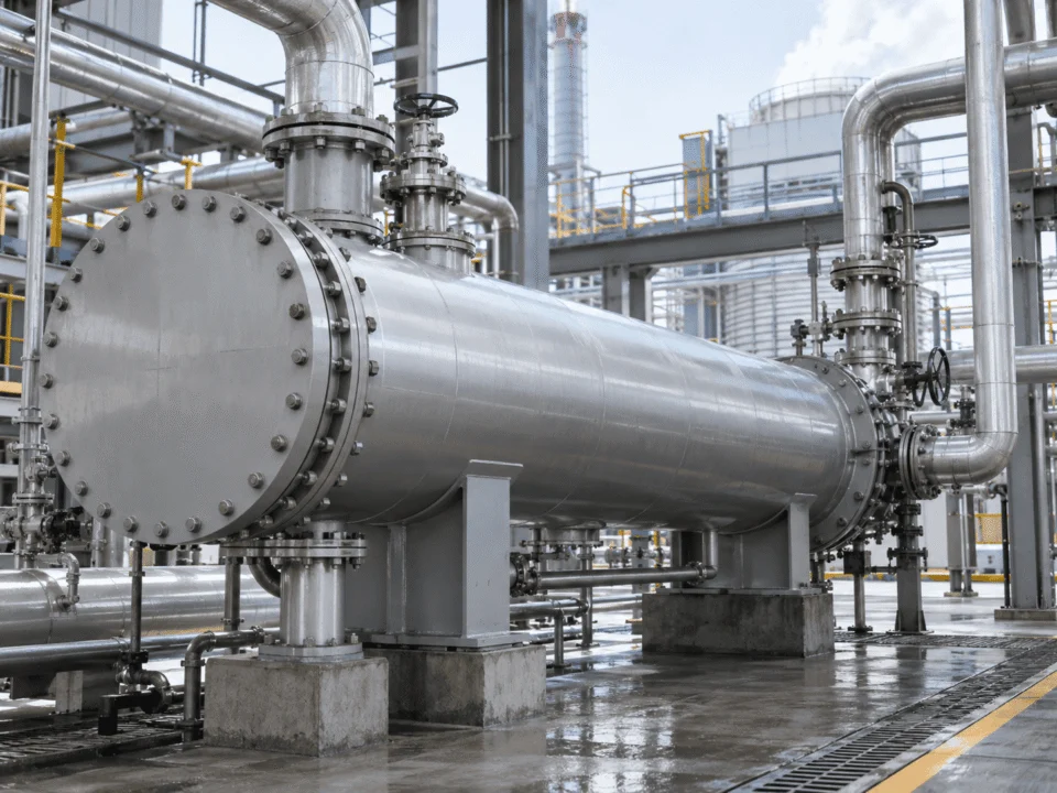
Power and industrial utilities shell and tube heat exchanger
POWER & INDUSTRIAL UTILITIES

Power and Industrial Utilities

Steam condensation Oil cooling Water heating Closed-loop cooling Waste heat recovery
Design focus

Reliability, pressure drop and long operating periods often dominate the balance between performance and maintainability.

SERVICE-FIRST SELECTION

A similar-looking exchanger can require a very different tube material, pass arrangement, baffle design, cleaning strategy or mechanical configuration when the service changes.

MANUFACTURING, INSPECTION & TESTING

A Good Thermal Design Still Has to Be Built Correctly

A shell-and-tube exchanger combines pressure-retaining components, thin heat-transfer tubes, numerous tube-to-tubesheet joints, internal supports and accurately positioned nozzles. Fabrication control matters at every stage.

QUALITY CONTROL BOARD

What is checked from material receipt to final documentation?

PROJECT-SPECIFIC
MATERIAL CONTROL

Material identity and traceability

Material identification and traceability can be maintained according to the applicable project and code requirements.

Material identification Certificate review Component traceability
WELDING CONTROL

Pressure-retaining weld execution

Pressure-retaining welds are produced according to the applicable welding procedures and agreed project requirements.

Welding procedure Dissimilar materials Clad / overlay details
DIMENSIONAL INSPECTION

Interfaces have to match the plant layout

Key dimensions can be checked against the approved drawing and agreed fabrication tolerances.

Nozzle orientation Support location Overall length Baffle spacing
NDE / NDT

Examination scope follows the project basis

Depending on code, material and project specification, suitable non-destructive examination methods can be incorporated into the inspection plan.

VT PT MT RT UT
PRESSURE & LEAK TESTING

Final pressure boundary verification

Hydrostatic testing and, where specified and permitted by the applicable code and approved procedure, pneumatic or additional leak-testing methods can be incorporated.

Hydrostatic test Leak test where required Test records
DIMENSIONAL CHECKPOINTS

Dimensions that matter after the exchanger arrives on site

Nozzle Orientation

Must align with the connected piping arrangement.

Support Location

Must match foundations, steelwork and installation geometry.

Bundle Dimensions

Influence assembly, shell clearance and maintenance access.

Tube Projection

Important to the selected tube-to-tubesheet joint detail.

Baffle Spacing

Connects fabrication accuracy with the thermal and mechanical design.

Overall Length

Affects transport, installation and maintenance clearance.

PROJECT DOCUMENTATION

Quality control should leave a usable record.

A documentation package can be prepared around the agreed project scope, combining relevant drawings, material records, inspection results and test documentation.

Approved Drawings Material Records Inspection Reports NDE / NDT Records Pressure Test Records Project-Specific Documents
PROCESS DATA

What We Need to Size Your Heat Exchanger

“20 m² heat exchanger” is not enough information. Heat-transfer area is an output of the design process, not the only input.

If you already have a completed exchanger datasheet or drawing, send it for review. If you are starting from process conditions, the information below gives us a much stronger basis for thermal and mechanical engineering.

PROCESS DATASHEET

Hot Side and Cold Side Data Should Be Defined Separately

Better Inputs → Better Engineering
HOT SIDE Process Stream A
Fluid / CompositionWhat is flowing?
Flow RateMass or volumetric flow
Inlet TemperatureHot-side inlet condition
Required Outlet TemperatureTarget leaving condition
Operating PressureNormal operating pressure
Design PressureMechanical design basis
Allowable Pressure DropAvailable ΔP
Fouling / SolidsDeposit or solids tendency
Corrosion InformationMaterial compatibility input
COLD SIDE Process Stream B
Fluid / CompositionWhat is flowing?
Flow RateMass or volumetric flow
Inlet TemperatureCold-side inlet condition
Required Outlet TemperatureTarget leaving condition
Operating PressureNormal operating pressure
Design PressureMechanical design basis
Allowable Pressure DropAvailable ΔP
Fouling / SolidsDeposit or solids tendency
Corrosion InformationMaterial compatibility input
PHYSICAL PROPERTIES

Property data improves the quality of the thermal calculation.

If these values are available from your process data, include them for each stream. They can materially change heat-transfer and pressure-drop calculations.

Density

Influences velocity and hydraulic behavior.

Viscosity

Affects Reynolds number, pressure drop and heat transfer.

Specific Heat

Connects flow rate with the required heat duty.

Thermal Conductivity

Influences convective heat-transfer behavior.

Phase / Vapor Fraction

Important for condensing, boiling and mixed-phase service.

Solids Content

Can change fouling risk, velocity limits and cleaning strategy.

MECHANICAL & PROJECT REQUIREMENTS

Thermal data alone does not define the equipment.

Design Temperature

Maximum / minimum mechanical design conditions.

Material Restrictions

Required or prohibited materials and alloy preferences.

Design Code

Applicable code or customer specification where already defined.

Preferred Configuration

Fixed, U-tube, floating head or existing replacement basis if specified.

Orientation

Horizontal / vertical and installation constraints.

Nozzle / Flange Standard

Plant piping interface and connection requirements.

Cleaning Method

Mechanical, chemical, CIP or maintenance strategy.

Maintenance Space

Bundle pull space, lifting access and surrounding equipment.

Inspection Requirements

NDE / NDT, witness points or customer inspection scope.

Documentation Requirements

Drawings, material records, inspection and test documents.

Installation Environment

Indoor, outdoor, corrosive atmosphere or other site conditions.

Existing Equipment Data

Nameplate, old drawing or current operating data for replacement projects.

IF SOME DATA IS MISSING

Send what you already have.

A process datasheet, PFD, P&ID, existing exchanger nameplate, drawing or current operating conditions can help establish the next engineering questions.

FAQ

Frequently Asked Questions About Shell and Tube Heat Exchangers

These questions usually appear before quotation because configuration, cleaning, pressure drop, materials and maintenance requirements can change the exchanger significantly.

Which is better: fixed tubesheet, U-tube or floating head?

None is automatically better. Fixed tubesheet exchangers provide relatively simple construction, U-tube exchangers accommodate differential expansion efficiently, and floating-head exchangers provide strong maintenance access and thermal movement capability.

The correct choice depends on fouling, cleaning requirements, temperature difference, pressure, fluid allocation and maintenance strategy.

Can you manufacture from an existing drawing?

Yes. Existing drawings and datasheets can be used as the starting point for quotation and engineering review.

Important design conditions should still be checked before fabrication, especially when the existing exchanger has recurring fouling, corrosion, vibration or performance problems.

Can shell and tube heat exchangers be customized?

Yes. Shell diameter, tube length, tube material, shell material, tubesheet construction, number of passes, baffle arrangement, nozzle orientation, support arrangement and overall configuration can be adapted to the project requirements.

Final geometry should follow the process and mechanical design rather than a catalog size alone.

What materials can be used?

Common project materials include carbon steel and stainless steels such as 304/304L and 316/316L.

Duplex stainless steel, titanium and other project-specified alloys can also be considered where corrosion conditions justify them. Different materials can be used for the shell, tubes, tubesheet and channels when appropriate.

How do I know whether the tube bundle needs to be removable?

Consider what happens when the exchanger becomes fouled. If the shell side requires mechanical access to the outside of the tubes, a removable bundle may be important.

If chemical cleaning is acceptable and the service is relatively clean, bundle removal may be less important. The available extraction space at the installation site must also be checked.

Does more heat-transfer area always improve performance?

No. Additional surface area can provide thermal margin, but changing the number of tubes can also change fluid velocity and pressure drop.

If velocity becomes too low, the exchanger may become more susceptible to fouling in some services. Area, velocity, pressure drop and fouling should therefore be evaluated together.

Why is allowable pressure drop important?

Pressure drop is part of the energy required to move fluid through the exchanger.

A geometry that provides strong heat transfer may still be unsuitable if the pump or process cannot supply the required pressure. Providing allowable ΔP on both shell side and tube side gives the designer much more freedom to optimize the exchanger correctly.

Can you design for high-pressure or high-temperature service?

Shell-and-tube exchangers can be engineered for demanding pressure and temperature conditions, but there is no useful universal pressure or temperature limit for a custom exchanger.

The practical design depends on material, diameter, wall thickness, joint design, tubesheet design, configuration, applicable code and the complete operating conditions.

ENGINEER THE EXCHANGER AROUND THE PROCESS

Send Us the Operating Conditions — Not Just the Required Area

A shell-and-tube heat exchanger should balance heat duty, pressure drop, fluid velocity, fouling, corrosion, cleaning, thermal expansion and mechanical design.

Send your process conditions, existing datasheet or equipment drawing. We can use that information to define the exchanger configuration and manufacturing requirements around the actual service.

USEFUL STARTING INPUTS
Fluid & Composition

Hot side and cold side media

Flow Rate

Mass or volumetric flow

Temperature Program

Inlet and required outlet conditions

Design Conditions

Pressure and temperature basis

Allowable ΔP

Shell-side and tube-side limits

Cleaning & Fouling

Maintenance and deposit behavior

Datasheet PFD / P&ID Existing Drawing Nameplate Data
Scroll to Top
DRAWING & FILE REVIEW

Send Your Drawings

Upload your drawings, datasheets or existing specifications. Our engineering team will review the files and respond with technical feedback.

Engineering Review

Drawings, specifications and process requirements

Confidential File Handling

Project files are used only for technical review and quotation

Faster Technical Feedback

Clearer inputs help us respond more accurately and efficiently

DRAWING & FILE REVIEW

Send Your Drawings

Upload your drawings, datasheets or specifications. Our engineering team will review your files and provide technical feedback.

Contact Form Demo (#3)
Project Protected NDA available
12h Response
ASME / PED
AFTER SUBMISSION
01 Review
→
02 Confirm
→
03 Quote
TECHNICAL QUOTATION

Get a
Technical Quote

Tell us what you need. Our engineering team will review your requirements and respond within 12 hours.

Engineered for Your Application

From concept to certified manufacturing

Global Compliance

ASME, PED and other international standards

Expert Support

Direct access to our engineering team

TECHNICAL QUOTATION

Get a Technical Quote

Tell us what you need. Our engineering team will review your requirements and respond within 12 hours.

Contact Form Demo
Project Protected NDA available
12h Response
ASME / PED
AFTER SUBMISSION
01 Review
→
02 Confirm
→
03 Quote