
Horizontal Pressure Vessels
Custom-engineered horizontal pressure vessels for process storage, separation, buffering, and gas-liquid service, designed around your operating conditions, layout constraints, and project requirements.
Configure vessel diameter and length, saddle positions, nozzles, manways, internals, materials, corrosion allowance, inspection scope, and transport limits around the actual project.
Built around process duty and available footprint
Support positions considered with vessel loading
Nozzles, manways, internals, and connections to suit the project
NDT, pressure testing, and project documentation as required
A Horizontal Vessel Is Designed as One Mechanical System
Horizontal pressure vessel design is not only a shell-thickness calculation. Once the vessel is carried on saddles, the shell, supports, nozzles, piping interface, and installation envelope begin to influence one another.
Operating, empty, hydrotest, transport, and thermal conditions should be considered together before the support arrangement and final vessel geometry are frozen.
Diameter-to-length ratio, head geometry, wall thickness, openings, internals, corrosion allowance, and fabrication details are developed around the required pressure boundary and process volume.
Saddle spacing affects support reactions, longitudinal bending, and local shell stress. Fixed and sliding support concepts may also be required where thermal movement or long vessel length becomes significant.
Nozzle orientation, support elevation, drainability, maintenance access, piping clearance, insulation, and transport limits all affect whether the finished vessel can be installed and operated as intended.
The sections that follow separate these decisions into process duty, configuration, support engineering, materials, fabrication, inspection, and site-delivery considerations.
What the Vessel Must Do Determines How It Should Be Configured
Horizontal vessels can serve very different process duties. The correct geometry, nozzle arrangement, internal components, liquid level range, and support design should follow the actual operating objective rather than a generic vessel layout.
Depending on the duty, sizing may be governed by vapor disengagement, liquid hold-up, residence time, pressure cycling, level-control range, or a combination of these conditions.
Provide vapor disengagement and controlled liquid collection
In gas-liquid service, the horizontal arrangement can provide useful liquid surface area and hold-up volume while maintaining a defined vapor space above the liquid level.
Inlet momentum, normal and high liquid levels, vapor outlet location, liquid draw-off, drainability, and access for internal devices.
Inlet devices, calming arrangements, baffles, or mist-elimination components may be used when the process duty requires them.
The vessel should be evaluated for both separation performance and the mechanical effects of operating and hydrotest liquid loads.
Absorb short-term flow variation and stabilize the connected system
Receiver and buffer vessels provide usable volume between upstream and downstream equipment, helping the system tolerate fluctuations in supply, demand, or pressure.
Required working volume, operating pressure range, connection sizes, drain points, venting provisions, and maintenance access.
Repeated pressure or level changes may influence the design basis, depending on the expected operating cycle and project specification.
Nozzle loads, support reactions, and available installation space should be reviewed together with the required vessel volume.
Create controlled liquid inventory for process fluctuations
Surge and accumulation service typically depends on the usable liquid volume between defined operating levels rather than total vessel volume alone.
Normal level, low and high operating levels, usable surge volume, outlet location, drainage, and level-instrument connections.
Residence time and response to changing inlet or outlet flow may be more important than maximizing geometric capacity.
Operating liquid distribution and hydrotest condition can produce very different support and shell loading cases.
Manage rapid vapor release while limiting liquid carryover
Flash and knock-out duties require enough internal space for the entering stream to lose momentum and for separated liquid to collect below the vapor outlet zone.
Feed entry, vapor disengagement space, high liquid level, vapor outlet placement, liquid outlet, and possible entrainment-control internals.
Carryover risk and inlet momentum can be as important as nominal vessel volume when selecting the internal arrangement.
Nozzle reinforcement and local loading should be checked where large process connections or heavy piping are expected.
Maintain pressurized process inventory with practical access and drainage
Where the vessel primarily provides pressurized hold-up, the design should balance required working volume with installation length, support spacing, nozzle access, and future maintenance.
Working capacity, allowable footprint, fill and withdrawal connections, venting, drainage, manway location, and insulation clearance.
A longer vessel may reduce diameter but can increase transport, support, piping, and thermal-movement considerations.
The selected length and diameter should be reviewed against fabrication capability, shipment envelope, and site installation constraints.
Choose the Orientation Around Process Duty, Plot Space, and Installation Reality
A horizontal vs. vertical pressure vessel comparison should start with what the vessel must do and how it must fit the site. Neither orientation is universally better. Liquid inventory, separation behavior, available footprint, support arrangement, piping access, transportation, and erection all influence the final choice.
Uses more ground length but keeps the vessel profile lower, which can simplify access where building height or overhead clearance is limited.
Uses less plot area but increases overall height and may require more attention to structural support, lifting clearance, platforms, and erection planning.
Can provide a broad liquid surface and practical hold-up volume over a relatively low vessel height, which can be useful for receivers, surge service, and some separation duties.
Can provide liquid inventory within a smaller footprint, but liquid level changes occur over vessel height rather than vessel length and should be matched to the control strategy.
May be advantageous where gas-liquid disengagement needs a relatively large interfacial area together with liquid hold-up below the vapor space.
May suit duties where a compact plot area, vertical flow path, or gravity-driven internal arrangement better matches the separation mechanism.
Manways, side nozzles, drains, and instruments can often be arranged at accessible elevations along the vessel length, subject to piping and insulation clearance.
Nozzles and access points may be distributed over a greater height, which can increase the need for ladders, platforms, elevated piping support, or maintenance lifting access.
Saddle reactions, longitudinal bending, shipping length, and fixed or sliding support behavior become important as vessel length and operating weight increase.
Skirt, leg, or lug support concepts transfer loads differently, while vessel height can place more emphasis on wind, seismic, lifting, and site erection requirements.
If both layouts are technically possible, compare process performance, footprint, support loads, maintenance access, shipment limits, and erection constraints together. The next engineering step is then to define the horizontal vessel inputs around the selected duty and site envelope.
Good Vessel Design Starts With the Right Engineering Inputs
A horizontal pressure vessel should be developed from the actual process and site conditions, not from a generic shell size. The more clearly the design basis is defined before detailed engineering begins, the easier it is to control geometry, support loads, nozzle arrangement, fabrication scope, and project risk.
Not every detail has to be finalized on day one. But the governing pressure, temperature, fluid, usable volume, support environment, nozzle interfaces, and installation limits should be identified early enough to prevent redesign later.
Service fluid, phase behavior, operating objective, required retention or hold-up, normal liquid level, upset condition, and expected operating pattern establish what the vessel is actually being asked to do.
These inputs influence vessel diameter and length, vapor space, liquid inventory, internal arrangement, drainability, and the location of process connections.
Operating pressure and temperature, design pressure and temperature, vacuum or external pressure where applicable, relief-case assumptions, and credible transient conditions should be identified clearly.
These conditions drive pressure-boundary calculations and can also affect material selection, flange rating, thermal movement, testing requirements, and local reinforcement.
Required working capacity, normal operating level, low and high liquid levels, vapor space, surge allowance, and any minimum drainable inventory should be distinguished from total geometric volume.
The usable level range affects length-to-diameter selection, nozzle elevations, instrument connections, internal clearances, and support loading under different fill conditions.
Nozzle size, rating, orientation, projection, mating-pipe direction, allowable external loads, instrument connections, manways, drains, vents, and removable items all affect the final arrangement.
Early interface definition reduces clashes between piping, saddles, internals, insulation, access zones, lifting points, and reinforcement details.
Support elevation, foundation spacing, anchor arrangement, operating weight, hydrotest condition, thermal movement, wind or seismic basis where required, and maintenance access should be included in the design inputs.
These inputs affect saddle position, fixed and sliding behavior, anchor loads, shell stress near supports, baseplate details, and the interface with civil or structural work.
Required inspection scope, documentation level, surface treatment, insulation attachments, shipping dimensions, lifting restrictions, site access, and delivery orientation can all influence how the vessel is detailed and manufactured.
A design that works on paper still has to be fabricated, inspected, transported, lifted, installed, and connected without avoidable field modification.
When some inputs are still open, they should be listed as design assumptions rather than left implicit. That keeps the quotation, engineering review, and later drawing approval aligned around the same design basis.
Turn the Design Basis Into a Buildable Vessel Configuration
Once the process duty and governing design inputs are defined, the next step is to translate them into a practical vessel arrangement. Geometry, openings, access, internals, drainage, and external attachments should be coordinated before the fabrication drawing is frozen.
Every feature should have a process, mechanical, inspection, or maintenance reason.
Avoid adding connections or internal details simply because they appeared on a previous vessel. Each feature changes fabrication, inspection, access, cost, or future maintenance.
Diameter, tangent-to-tangent length, head geometry, overall length, orientation of seams, and required clearances are coordinated around working volume, pressure design, fabrication practicality, shipment envelope, and site space.
Confirm that the selected diameter and length still leave room for nozzles, manways, insulation, lifting, and installation access.
Process nozzles, vents, drains, instrument connections, relief connections, manways, and removable items should be positioned around process function and actual piping direction rather than arranged only for drawing symmetry.
Review access, reinforcement spacing, internal clashes, insulation clearance, piping loads, and maintenance removal space.
Inlet devices, baffles, mist-elimination components, dip pipes, distribution pipes, weirs, calming devices, or other internals should only be added where the service requires them and where inspection or replacement remains practical.
Confirm internal support details, removal path, welding access, inspection reach, and whether internals must be removable through the manway.
Drain location, venting, low-point management, lifting lugs, earthing provisions, insulation clips, nameplate brackets, platforms, ladders, and other external attachments should be coordinated with the final operating and site arrangement.
Make sure external details do not conflict with saddles, piping, insulation, transport restraints, lifting points, or field access.
A cleaner vessel arrangement is usually easier to fabricate, inspect, insulate, transport, install, and maintain. Complexity should be added only when the process or project genuinely requires it.
After the vessel arrangement is defined, saddle location and support behavior can be checked against the real geometry and load cases.
Support Design Must Follow the Real Vessel Geometry and Load Cases
Horizontal vessels transfer shell weight, liquid weight, piping loads, thermal movement, and test loads into the foundation through the saddle system. Saddle location and support behavior should therefore be checked against the actual vessel arrangement rather than treated as a late fabrication detail.
The drawing is conceptual. Final saddle location, anchor arrangement, shell reinforcement, and movement allowance depend on vessel geometry, material, load cases, and project requirements.
Saddle Spacing & Shell Stress
Saddle positions influence support reactions, longitudinal bending, circumferential shell stress, and local stress around the support region. Moving the saddles changes more than foundation spacing; it changes how the shell carries the vessel.
Fixed & Sliding Support Behavior
A long horizontal vessel can expand and contract as temperature changes. Where the project requires it, one saddle may restrain the vessel while the other allows controlled longitudinal movement so thermal expansion is not unintentionally locked into the shell and foundation.
Hydrotest & Temporary Load Cases
Hydrostatic testing can create a vessel weight substantially higher than normal operating weight. Temporary test water, test orientation, internal supports, and local loading should be included when the saddle system and foundation reactions are checked.
Foundation & Piping Interface
Support elevation, anchor pattern, grout or baseplate requirements, piping loads, nozzle orientation, drain clearance, insulation thickness, and maintenance access should be coordinated with the civil and piping layouts before fabrication drawings are released.
The support system is part of the pressure-vessel design, not a separate steelwork afterthought. Early coordination between vessel, piping, structural, and site teams helps prevent anchor mismatches, restricted thermal movement, drainage problems, and field modification.
Material Selection Should Follow the Fluid, Temperature, Cleaning, and Corrosion Mechanism
The vessel material is not selected by pressure alone. Process chemistry, contaminants, operating temperature, wet and dry phases, cleaning method, expected corrosion mechanism, fabrication route, and required service life all influence the final material strategy.
Common approaches should be treated as starting points for engineering review, not automatic selections.
Carbon steel can be a practical choice where the service is compatible with the material and corrosion can be managed through operating control, corrosion allowance, coating, lining, or other project-specific protection.
General corrosion rate, water content, oxygen, contaminants, shutdown condition, coating compatibility, and inspection access.
Stainless steels may be selected where corrosion resistance, cleanliness, product purity, or cleaning requirements justify them, but grade selection should consider the actual chemical environment rather than the stainless-steel label alone.
Chlorides, temperature, pitting or crevice risk, cleaning chemicals, weld condition, surface finish, and possible contamination.
Duplex or higher-alloy materials may be considered when the service requires greater resistance to specific corrosion mechanisms or higher strength, provided welding, heat input, fabrication control, and inspection requirements are addressed.
Service chemistry, temperature limits, welding procedure, filler selection, ferrite or phase-balance requirements, and project qualification scope.
Where full-thickness corrosion-resistant alloy is not the preferred project approach, clad plate, weld overlay, lining, or coating may be evaluated to separate pressure-retaining strength from corrosion protection.
Bonding or attachment method, edge details, nozzle transitions, holiday testing, repair access, thermal cycling, and long-term maintainability.
Material selection should be documented together with the assumed fluid composition, temperature range, corrosion mechanism, corrosion allowance or protection system, fabrication requirements, and inspection plan so that procurement and engineering are working from the same basis.
Define the Code Basis and Quality Scope Before Fabrication Starts
A technically correct pressure vessel still needs a clearly defined construction code, welding basis, inspection scope, testing requirements, and documentation package. These requirements should be agreed before drawings and fabrication plans are released.
Expand each gate to review the information that should be fixed before the next stage.
Code, Materials & Design Basis
Confirm the governing construction code, project specification, design pressure and temperature, corrosion allowance, materials, impact-test requirements where applicable, design life assumptions, and any purchaser-specific requirements before detailed fabrication drawings are finalized.
Material specifications, traceability level, allowable substitutions, certification requirements, and documentation language.
Late changes to material grade, code edition, or certification scope can affect calculations, welding, inspection, lead time, and cost.
Welding & Fabrication Control
Welding procedures, welder or operator qualifications, joint preparation, fit-up, forming, heat treatment where required, dimensional control, attachment welding, and repair procedures should follow the applicable construction basis and approved fabrication plan.
WPS and PQR basis, welder qualifications, consumables, preheat, interpass control, PWHT requirements, weld mapping, and repair records.
Do not assume PWHT, special weld procedures, or alloy fabrication controls are included unless the requirement is defined in the technical scope.
NDE, Inspection & Hold Points
Visual examination and any required RT, UT, MT, PT, or other nondestructive examination should be defined by the governing code, the design assumptions, and the purchaser specification. Inspection timing matters because some areas become inaccessible as fabrication progresses.
NDE method and extent, acceptance criteria, inspector qualification, hold or witness points, repair re-examination, and third-party involvement.
Do not assume “full NDE” means the same thing on every project. State the required method, extent, acceptance basis, and witnessing scope.
Pressure Test & Final Documentation
The final pressure test, dimensional verification, visual inspection, nameplate or marking requirements, preservation, and documentation package should close the same quality plan that began with the design basis.
Applicable hydrostatic or pneumatic test requirements, test medium, test condition, drying or preservation, final dimensions, and release status.
Typical project records may include material certificates, approved drawings, welding qualifications, NDE reports, heat-treatment records, test reports, and final manufacturing documentation as specified.
Inspection quality is easier to control when the acceptance basis is defined before manufacturing starts. The drawing, quality plan, inspection scope, and final document index should all point back to the same project requirements.
Delivery Planning Starts Before the Vessel Leaves the Workshop
A horizontal pressure vessel is not finished when fabrication ends. Shipping dimensions, lifting points, center of gravity, temporary restraints, preservation, foundation readiness, and site access all affect whether the vessel can move from workshop release to final installation without avoidable rework.
What should be confirmed before dispatch
Overall length, diameter, shipping height, support spacing, projection of nozzles and attachments, empty shipping weight, and any removable transport items should match the approved transport basis.
Lifting lugs or trunnions, lift orientation, rigging clearance, temporary braces, shipping saddles, and transport restraints should be coordinated with the actual handling method.
Flange faces, openings, machined surfaces, internal cleanliness, coatings, stainless surfaces, and exposed instruments or fittings should be protected for the expected transport and storage environment.
The shipping package should align with the approved drawing, packing list, release status, handling instructions, and any project-specific documentation required before the equipment leaves the workshop.
What should be ready before the vessel arrives
Support centerlines, foundation elevations, anchor locations, sliding-saddle details, grout allowance, and access around the supports should match the released vessel drawings.
Site entry, road width, turning radius, overhead restrictions, laydown space, crane setup area, lift radius, and final set-down path should be confirmed before delivery.
The installed orientation should leave room for nozzle connections, drains, insulation, manway opening, internal removal, platforms, and future maintenance work.
After setting the vessel, confirm support contact, anchor condition, intended sliding freedom, level or slope where specified, shipping-restraint removal, and visible transport damage before final piping connection.
The most expensive logistics problems usually appear at interfaces: a nozzle that exceeds the shipping envelope, a saddle that does not match the foundation, a lift point that conflicts with rigging, or a vessel that reaches site before the access route is ready. Those interfaces should be resolved before dispatch.
Horizontal Pressure Vessels Across Process Industries
The same horizontal shell orientation can serve very different duties from one industry to another. Process fluid, pressure, temperature, corrosion risk, cleaning requirements, operating cycle, and site layout determine how the vessel should actually be configured.

Chemical Processing
Horizontal vessels can be configured for receiver, buffer, surge, hold-up, and phase-separation duties where fluid compatibility, corrosion control, drainage, and nozzle layout require close attention.
Chemical industry
Petrochemical
Knock-out, receiver, accumulator, surge, and separation services can benefit from horizontal geometry when liquid hold-up, vapor space, level range, and process connections must be balanced within the plant layout.
Petrochemical industry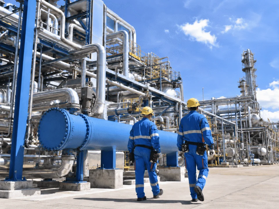
Oil & Gas
Gas-liquid separation, knock-out, condensate accumulation, buffering, and pressurized hold-up may place additional focus on pressure cycling, support reactions, piping loads, transport, and field installation.
Oil & gas industry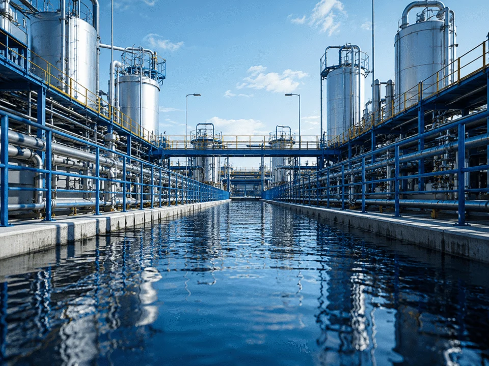
Water Treatment
Pressurized water, air, buffer, and utility duties may use horizontal vessels where site height, usable volume, service access, coating or lining requirements, and drainability shape the final configuration.
Water treatment
Pharmaceutical
Horizontal receivers and utility vessels may be selected where the layout benefits from a low profile, while material grade, cleanliness, surface condition, drainage, and maintenance access remain service-specific.
Pharmaceutical industry
New Energy
Process-gas, liquid-buffer, receiver, and separation duties in new-energy systems can require project-specific materials, pressure design, nozzle interfaces, support details, and transport planning.
New energyIndustry context changes the vessel design basis. The process duty should be defined first, then the horizontal vessel geometry, materials, supports, inspection scope, and site interfaces should be developed around that service.
Compare More Than Vessel Size and Price
Two quotations can describe vessels with similar dimensions while including very different engineering, inspection, support, documentation, and delivery scopes. Before purchase, confirm that the offers are technically comparable and based on the same project assumptions.
The best comparison is made on a common technical basis. When suppliers are quoting against different assumptions, the commercial comparison is not yet complete.
Send Enough Project Data to Quote the Vessel on the Right Basis
A useful RFQ does not need every detail to be final, but it should make the process duty, governing conditions, key interfaces, quality scope, and site constraints visible. Missing items can then be identified as assumptions instead of being hidden inside the quotation.
Provide the confirmed information first, then mark anything still pending.
Process & Design Basis
Receiver, buffer, surge, separation, knock-out, hold-up, or other defined service.
Liquid, gas, two-phase service, composition, contaminants, solids, and any hazardous or corrosive characteristics.
Normal operating conditions plus design pressure, design temperature, and vacuum or external-pressure requirement where applicable.
Required working volume, normal liquid level, low and high levels, surge volume, residence time, or other sizing basis.
Mechanical Configuration
Material grade, corrosion allowance, cladding, lining, coating, surface finish, or any project-specific metallurgy requirements.
Preferred diameter or length, available plot space, elevation constraints, orientation, insulation allowance, and shipment envelope if known.
Nozzle schedule, flange rating, orientation, manways, vents, drains, instruments, removable items, and maintenance clearances.
Required internals, saddle arrangement, support elevation, fixed or sliding concept, anchor interface, and foundation constraints.
Code, Inspection & Deliverables
Required code, edition, certification or stamping scope, purchaser specification, and jurisdictional requirements.
NDE methods and extent, hold or witness points, third-party inspection, PWHT where required, and pressure-test expectations.
Calculation package, drawings, material certificates, welding records, NDE reports, test reports, final data book, and required language.
Required drawing stages, review cycle, document format, purchaser approval points, and any release conditions before fabrication.
Site, Transport & Commercial Notes
Maximum shipping dimensions, weight limitations, route restrictions, removable attachments, packaging, and preservation requirements.
Foundation interface, available crane access, installation space, ambient conditions, wind or seismic basis where required, and storage conditions.
Clarify what is supplied by the vessel manufacturer and what remains with piping, civil, structural, insulation, instrumentation, or site contractors.
Required delivery date, destination, Incoterms where applicable, inspection timing, document milestones, and any project shutdown window.
A stronger RFQ shortens clarification cycles and reduces the chance of comparing quotations built on different assumptions. The goal is not to provide more paperwork; it is to make the engineering basis visible.
Horizontal Pressure Vessel FAQs
These questions summarize the decisions that most often affect vessel selection, support design, sizing, materials, quotation scope, and RFQ preparation.
When is a horizontal pressure vessel preferred over a vertical vessel?
A horizontal arrangement is often considered when the process needs useful liquid hold-up, a relatively low equipment profile, practical side access, or a broad liquid surface for certain separation duties. The final choice should still be checked against plot space, support loads, piping, transport, erection, and maintenance access.
How are saddle positions selected on a horizontal pressure vessel?
Saddle positions are selected from the actual vessel geometry and load cases rather than from a fixed percentage rule alone. The review should consider shell and head geometry, operating and hydrotest weight, support reactions, longitudinal bending, local shell stress, thermal movement, anchor behavior, and the foundation interface.
Why can the hydrotest condition be more demanding than normal operation?
During hydrostatic testing, the vessel may be filled with test liquid to a condition that produces a much higher total weight than normal service. That temporary condition can govern saddle reactions, baseplate loads, foundation loads, and local shell checks even when the operating case is less severe.
What information is needed to size a horizontal pressure vessel?
Useful sizing inputs include the process duty, fluid and phase behavior, operating and design pressure and temperature, required working volume, liquid-level range, surge or hold-up requirement, residence time where relevant, vapor space, and any separation-performance requirement. Site and transport limits can also influence the final diameter-to-length ratio.
Can nozzle positions be changed after the vessel size is selected?
Nozzle positions can often be adjusted during detailed engineering, but late changes may affect reinforcement spacing, internals, saddles, insulation, access, piping loads, drainage, and fabrication drawings. It is better to coordinate nozzle orientation and connected piping before the final arrangement is frozen.
Which materials are commonly used for horizontal pressure vessels?
Carbon steel, stainless steel, duplex or higher-alloy materials, and clad, lined, or coated constructions may all be considered depending on the service. Material selection should follow the actual fluid chemistry, temperature, corrosion mechanism, cleaning method, fabrication requirements, expected service life, and project specification.
What should be confirmed before comparing supplier quotations?
Compare the same design basis, material scope, saddle and support scope, nozzle and internal arrangement, construction code, inspection and NDE scope, testing, documentation, transport limits, exclusions, and approval requirements. Similar vessel dimensions do not necessarily mean the quotations include the same technical scope.
What should I send for a horizontal pressure vessel RFQ?
Send the confirmed process and design conditions first, then include any datasheet, PFD or P&ID, general arrangement, nozzle schedule, material or inspection specification, foundation information, transport limits, and site constraints you already have. Items that are still open should be identified as assumptions or pending inputs.
Project-specific answers depend on the actual process duty, design conditions, material requirements, support arrangement, inspection scope, and site constraints. Those inputs should be reviewed together before the final vessel configuration is approved.
Need a Horizontal Pressure Vessel Built Around Your Actual Project Conditions?
Send your process duty, design pressure and temperature, required capacity, material preference, nozzle information, and site constraints. If some data is still open, we can identify the missing inputs before the quotation basis is fixed.
Datasheets, P&IDs, GA drawings, nozzle schedules, or even an early project sketch can help speed up the technical review.