
ChannelVessel Intelligent Equipment Co., Ltd. Contact Us
Custom Industrial Towers

Stripping Towers for Air & Steam Service

ChannelVessel supplies custom stripping towers for transferring target compounds from liquid streams into a gas or vapor phase. Discuss air stripping, steam stripping, packed or trayed construction, and the equipment scope required for your process.

Start with the feed composition, required outlet concentration and available utilities. We coordinate the tower configuration and fabrication scope around the agreed project basis—not a one-size-fits-all removal claim.

Air & Steam Service
Packed & Trayed Options
Project-Specific Fabrication

Share your process conditions, equipment datasheet or existing tower drawing.

Custom industrial stripping tower manufactured for air and steam stripping service
Built Around Your Duty Feed data, outlet target, utilities and fabrication scope.
Define the Separation Duty

What Are You Trying to Remove?

Specify the separation task before selecting the tower. A groundwater VOC duty, an ammonia-bearing wastewater and a solvent-recovery stream should not share a generic performance specification.

VOC Removal

Volatile Organic Compounds

Provide the individual compounds, inlet concentrations and required outlet limits.

Main question: can air stripping meet every specified component limit?
Ammonia Duty

Ammonia Removal or Recovery

Define the ammonia reporting basis, pH, temperature and complete water analysis.

Main question: how will released ammonia be captured and managed?
Solvent Duty

Solvent Removal

State solvent composition, water content and whether recovery is part of the objective.

Main question: is the target treated liquid, recoverable solvent, or both?
Degassing

Dissolved-Gas Removal

Identify the gas, dissolved concentration and downstream handling requirements.

Main question: what transfer and vent-handling conditions are required?
Sour Water

Sour-Water Treatment

Provide ammonia, hydrogen sulfide, hydrocarbons, solids and pretreatment information.

Main question: what dedicated process and overhead-treatment scope is required?

Stripping is not a substitute for every treatment step. Free oil, solids and scale-forming constituents may require pretreatment, while nonvolatile dissolved contaminants need separate evaluation rather than an assumed stripping guarantee.

Select the Stripping Route

Air Stripping or Steam Stripping?

Air stripping uses an air stream to carry volatile compounds away from the liquid. Steam stripping uses steam or generated process vapor and normally requires a closer review of heat supply, overhead handling and liquid composition.

Air stripping and steam stripping process comparison diagram
Route A

Air Stripping

Air Service
Starting assessment
Compound volatility in water at the proposed operating conditions.
Utility review
Blower, pumps and any heating or air-treatment requirements.
Overhead stream
Air containing the compounds transferred from the liquid phase.
Recovery review
Suitability of the selected off-gas treatment or recovery route.
Feed information
Component analysis, liquid flow and seasonal operating conditions.
Route B

Steam Stripping

Steam Service
Starting assessment
Vapor-liquid behavior at the proposed temperature and pressure.
Utility review
Direct steam or reboiler duty, pumps and cooling requirements.
Overhead stream
Vapor containing water and the compounds transferred from the feed.
Recovery review
Condensation, phase behavior and any additional separation requirement.
Feed information
Component analysis, thermal behavior and recovery specifications.

Neither route is universally better. Compare both against the same feed envelope, outlet targets and supply boundary. Atmospheric, vacuum and pressurized operation describe pressure conditions and should be specified separately from the choice of stripping medium.

Screen the Target Compound

Can Your Target Compound Be Effectively Stripped?

“VOC” is a category, not a complete design input. Identify each target compound and evaluate its equilibrium behavior at the intended temperature and liquid composition before selecting the tower.

Reference Henry Constants at 25°C

Historical screening values from the U.S. EPA Air Stripper Design Manual. Use validated property data for the actual process conditions.

Hpc · atm·m³/mol
Compound
Hpc
Screening view
Tetrachloroethylene (PCE)
2.90 × 10⁻²
Higher gas-phase tendency
Trichloroethylene (TCE)
9.10 × 10⁻³
Relatively favorable
Toluene
6.68 × 10⁻³
Relatively favorable
Benzene
5.50 × 10⁻³
Relatively favorable
Acetone
2.50 × 10⁻⁵
Much lower gas-phase tendency
220× Benzene Hpc vs. acetone Hpc in this reference table

This shows why two compounds in the same broad “VOC” category can require very different gas rates, transfer area and operating conditions. It does not mean one tower needs exactly 220 times more air or packing.

Use the correct property basis

Henry constants appear in several conventions and units. Do not compare reciprocal or dimensionless forms directly with Hpc values. Concentrated solvents, reactive systems and ammonia also require a suitable thermodynamic or chemical-speciation basis.

Follow the Mass Transfer

How Stripping Works—and Where the Removed Compounds Go

In a countercurrent tower, liquid descends through the contacting section while gas or vapor rises. Internals provide contact between the phases. Treated liquid leaves the bottom, while transferred compounds leave with the overhead stream.

Stripping tower process flow showing alternative off-gas treatment and condensation recovery routes

Overhead treatment is selected by vapor composition, concentration and recovery objective. The routes shown are alternatives, not a universal configuration.

Air-Stripping Route

Gas-Phase Transfer
Feed Preparation Confirm flow, contaminants, temperature, solids and pretreatment requirements.
Countercurrent Contact Liquid moves downward while stripping air moves upward through the selected internals.
Treated Liquid Bottoms are verified against the agreed outlet concentration and sampling basis.
Off-Gas Handling The overhead air continues to the selected emission-control, recovery or approved discharge route.

Steam-Stripping Route

Vapor-Phase Transfer
Feed Conditioning Define heating, steam supply, feed temperature and the intended recovery objective.
Steam Contact Steam or generated vapor rises through the contacting section while liquid flows downward.
Bottoms Handling Stripped liquid leaves the tower for cooling, reuse, further treatment or downstream processing.
Overhead Recovery Overhead vapor may be condensed, separated or sent to another treatment step according to phase behavior and product requirements.
≠

Transferred does not mean destroyed. A stripping tower changes where the target compound is carried. The project must also define how the overhead stream, condensate and treated liquid are handled.

Define the Performance Target

Specify Outlet Concentration, Not Just Removal Efficiency

A headline removal percentage does not tell a buyer whether the treated liquid meets the required concentration. State both inlet and outlet values, with units and a defined sampling basis.

Illustrative Performance Target

Example Only
Liquid Flow 20 m³/h
Inlet Concentration 1,000 mg/L
Outlet Target 5 mg/L
Concentration Reduction
Calculated Outlet
Meets the 5 mg/L Example Target?
99.0%
10 mg/L
No
99.5%
5 mg/L
Exactly at the target, with no allowance for variability
99.9%
1 mg/L
Below the target
Required concentration reduction: (1 − 5 / 1,000) × 100 = 99.5%
Liquid-phase component removal at the 5 mg/L target: 20 × (1,000 − 5) / 1,000 = 19.9 kg/h
Required Reduction 99.5%

A “99% removal” claim would still leave 10 mg/L in this example and therefore miss the specified 5 mg/L outlet target.

Concentration decrease is not always component removal.

When inlet and outlet liquid flows differ, use a component mass balance. Dilution alone can lower concentration without removing the same proportion of contaminant mass.

Do not treat this calculation as a performance guarantee.

The example demonstrates how to define an acceptance target. Actual stripping performance depends on the feed, physical properties, operating conditions, internals and system design.

Translate Duty Into Geometry

What Determines Tower Diameter and Height?

Liquid throughput alone does not determine tower dimensions. The required flow area and contacting height are set by the separation task, gas and liquid loads, hydraulic limits and the selected internals.

Packed stripping tower cutaway showing tower diameter, active packing height and overall vessel height
D

Diameter: Provide Enough Flow Area

Tower diameter is selected through hydraulic evaluation of gas and liquid loading, pressure drop and flooding limits. A higher stripping-gas demand can increase the required diameter even when liquid throughput stays the same.

H

Packing Height: Provide Enough Transfer Duty

For a packed-column calculation using a consistent transfer-unit basis, active packing height depends on the height of a transfer unit and the number of transfer units required by the separation.

Active Packing Height = HTU × NTU
Σ

Overall Height Is More Than Active Packing

Allow additional space for liquid distributors, collectors, inlet zones, disengagement, liquid inventory, manways and maintenance access. A quotation for 6 m of active packing is not automatically a 6 m overall vessel.

Do not size the tower from flow alone. The final geometry should be checked against the complete process and mechanical design basis, including the selected internals and operating envelope.

Check the Hydraulic Window

Balance Gas/Liquid Ratio, Pressure Drop and Flooding

Increasing stripping gas can improve mass-transfer driving force, but it also raises vapor velocity, pressure drop and utility demand. The operating point must stay inside the hydraulic range of the selected internals.

More Gas Is Not a Free Performance Gain

Step Gas Flow ↑

Higher gas flow changes the gas-to-liquid operating ratio.

Effect Mass Transfer Changes

The driving force can improve, but the benefit depends on equilibrium and internals.

Hydraulics Pressure Drop ↑

Gas velocity and resistance through the contacting section increase.

Limit Flooding Risk ↑

Approaching flooding reduces stable countercurrent operation and available capacity margin.

Design for an operating window—not a single point.

Check minimum, normal and maximum gas and liquid loads. High-load capacity, pressure drop and low-load wetting all matter when selecting the internals and tower diameter.

Gas/Liquid Ratio Example

For an illustrative volumetric gas-to-liquid ratio of 50:1 and a liquid flow of 20 m³/h:

Gas Flow = 50 × 20 = 1,000 m³/h

State whether the gas flow is actual or normalized, together with reference temperature, pressure and wet/dry basis.

Why Pressure Drop Affects Blower Power

Using an illustrative actual gas flow of 1,000 m³/h and blower efficiency of 65%:

2 kPa System Rise ≈ 0.85 kW
5 kPa System Rise ≈ 2.14 kW

These are simplified shaft-power calculations, not motor selections. Total system resistance also includes connected equipment and ducting.

Flooding is a hydraulic limit, not an operating target. Keep adequate capacity margin and verify the selected packing or trays against the actual gas and liquid properties.

Choose Internals Around the Feed

Packed or Trayed? There Is No Universal Winner

Internal selection should follow the process duty, fouling tendency, pressure-drop allowance, turndown requirement and maintenance strategy—not a generic preference for one tower type.
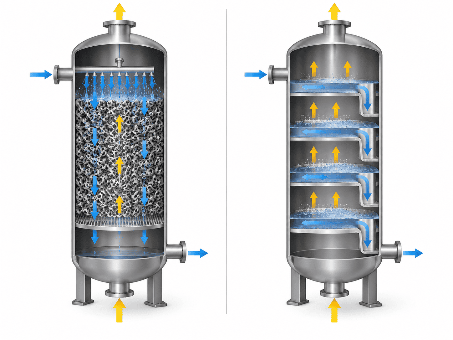
Packed and trayed stripping tower internals comparison

Packed Stripping Tower

Packing-Based Contact
Pressure drop
Evaluate packing type and size when low pressure drop is important.
Liquid distribution
Distributor quality and minimum wetting become part of the performance basis.
Fouling
Check packing openings, deposit risk and the practical method for bed cleaning or removal.
Maintenance
Plan access to distributors, support grids, collectors and replaceable packing sections.

Trayed Stripping Tower

Tray-Based Contact
Operating range
Check tray type and turndown against minimum, normal and maximum vapor and liquid loads.
Pressure drop
Evaluate the cumulative pressure drop across the full number of operating trays.
Fouling
Review anti-fouling tray geometry, openings and solids behavior for the actual feed.
Maintenance
Plan manway access to tray decks, valves, downcomers and other serviceable components.

Internals are part of the process design basis. Distributors, support grids, collecting devices, trays and access provisions should be defined together with the feed conditions and expected maintenance strategy.

Match the Design Basis to the Duty

Ammonia, VOC and Solvent Duties Need Different Design Bases

A single “stripping efficiency” does not describe every service. Chemistry, equilibrium behavior, temperature, reporting basis and downstream handling can all change what the tower must do.

Ammonia Duty

Define pH, Temperature and Reporting Basis

Ammonia stripping depends on the balance between dissolved ammonium and free ammonia. Specify whether the laboratory value is reported as nitrogen, NH₃ or another basis, together with pH and seasonal temperature.

EPA Reference pH 10.8–11.5
Historical Air Temp Data 20°C vs 10°C
The cited EPA fact sheet reports approximately 90–95% removal at 20°C air temperature and about 75% at 10°C for the conventional process it describes. Use this as evidence of seasonal sensitivity, not as a project guarantee.
VOC Duty

Specify Individual Compounds and Limits

A combined “total VOC” number can hide the component that actually controls tower design. Provide each regulated or process-critical compound, inlet concentration and required outlet concentration.

Different compounds can show very different equilibrium behavior even when they are all grouped under “VOC”. The design basis should follow the controlling components, not the category name.
Solvent & Sour Water

Define What Happens After Stripping

For solvent recovery, specify acceptable water content and downstream use. For sour water, identify ammonia, hydrogen sulfide, hydrocarbons and the intended overhead-treatment route.

The required tower and auxiliary equipment can change significantly depending on whether the objective is discharge, reuse, solvent recovery or downstream purification.

Ammonia removal is not the same as total-nitrogen removal. Other nitrogen species require separate evaluation and may need additional treatment steps.

Design for Real Operating Conditions

Plan for Fouling Before Performance Starts to Fall

Suspended solids, free oil, mineral deposits and biological growth can affect pressure drop, liquid distribution and stripping performance. Include fouling tendency in the original design discussion—not only after problems appear.

Technician inspecting stripping tower liquid distributor and packing through an open manway
Operating symptoms are starting points, not diagnoses.

A higher outlet concentration or rising pressure drop can have several causes. Compare actual operating data with a clean baseline before changing internals or increasing utility demand.

Observed Condition
Items to Investigate
Rising pressure drop
Packing or tray condition, deposit buildup, changed gas/liquid loads and downstream restrictions.
Higher outlet concentration
Feed composition, gas supply, temperature, pH where relevant, liquid distribution and fouling.
Unstable operation
Actual flow readings, liquid-level control, gas-supply stability and inlet variability.
Short cleaning intervals
Pretreatment, deposit composition, distributor condition and practical access to affected internals.
Establish a clean operating baseline.

Record flow, temperature, pressure drop, utility conditions and outlet concentration after commissioning or cleaning so later changes can be interpreted against known conditions.

Maintenance access belongs in the purchase specification. Define how distributors, packing supports, trays and other internals will be inspected or removed before fabrication is released.

Define the Equipment Package

Stripping Tower Configurations and Fabrication Scope

ChannelVessel can coordinate the tower shell, internals, access, supports and documentation around an approved equipment datasheet. Dimensional ranges describe a reference fabrication envelope—not a fixed stripping-tower model.

Reference Configuration and Fabrication Data

Final limits depend on material, pressure, temperature, internals, transport and the agreed design basis. Upper limits are not assumed to apply simultaneously.

Project-Specific Range
Tower Arrangement
Packed or trayed
Stripping Service
Air, steam, or another agreed process gas
Column Diameter
300–5,000 mm
Overall Tower Height
Up to 40 m
Shell Thickness
6–80 mm, subject to mechanical design
Shell Materials
Carbon steel, 304/304L, 316/316L; duplex stainless steel or special materials by specification
Design Pressure
Specified separately; include external-pressure or vacuum conditions where applicable
Liquid Capacity
State minimum, normal and maximum flow for the actual duty
Internals
Packing or trays, distributors, collectors, supports and duty-specific accessories
Construction & Shipment
Shop-fabricated or sectional arrangement to suit project and transport requirements

Define the Manufacturing Basis Before Release

Material & Corrosion Basis Confirm shell, internals, corrosion allowance and material certificates.
Mechanical Design Coordinate pressure, temperature, loads, supports, nozzles and transport constraints.
Fabrication & Welding Define welding documentation, dimensional checks and fabrication records.
Inspection & Testing Agree NDE, pressure or leak testing, third-party inspection and final documentation.
Do not treat standards as decorative labels.

Requested design-code compliance, certification, marking and third-party inspection should be identified explicitly in the quotation and purchase specification.

Compare Total Utility Demand

Compare Utility Demand, Not Only Tower Price

A stripping tower is only one part of the operating-cost picture. Compare quotations on the same basis for feed temperature, production schedule, utility conditions, overhead handling and heat-recovery scope.

Stripping tower utility and heat recovery process diagram with feed preheating, overhead condensation and cooling water

Air-Stripping Utility Scope

Review the complete connected system rather than only the tower shell.

Gas Supply Blower and ducting
Liquid Handling Feed and discharge pumps
Pretreatment Solids, oil or scale control where required
Overhead Off-gas treatment or recovery equipment
Pressure drop affects operating cost.

Blower power depends on actual gas flow and the total system pressure rise, including packing, connected equipment and ducting.

Steam-Stripping Heat Duty

Feed heating, steam or reboiler duty, cooling and overhead condensation can dominate operating cost.

Illustrative Sensible-Heating Load ≈ 1.39 MW

Assumes 20 m³/h water heated from 40°C to 100°C, density 1,000 kg/m³ and heat capacity 4.18 kJ/(kg·K).

This is not a steam-consumption figure.

The example excludes vaporization, heat losses and other process duties, and it does not deduct recovered heat.

Heat recovery should be evaluated on the actual temperature program. A feed–bottoms exchanger can reduce external heating demand when the process temperatures, allowable approach and fouling conditions make recovery practical.

Compare Quotations on the Same Basis

Make the Supply and Performance Boundaries Explicit

A vessel-fabrication quotation and a process-performance quotation are not interchangeable. Define responsibilities, terminal points, acceptance conditions and exclusions before comparing price.

Scope Item
What the Quotation Should Identify
Feed & Operating Basis
Accepted analysis, minimum / normal / maximum flow, temperature, pressure and expected variability.
Process Design
Responsibility for process calculations, physical-property basis, assumptions and any required testing.
Mechanical Design & Fabrication
Equipment boundary, design conditions, material, supports, nozzles, fabrication and documentation scope.
Tower Internals
Responsibility for selection, hydraulic verification, supply, installation and inspection of packing or trays.
Auxiliary Equipment
Included pumps, blowers, exchangers, condensers, receivers, piping interfaces and utility terminal points.
Overhead & Liquid Handling
Where each process stream terminates and who is responsible for recovery, treatment, reuse or disposal.
Controls & Commissioning
Included instruments, control functions, interlocks, commissioning scope and site support.
Performance Verification
Responsible party, measured targets, operating conditions, sampling points, analytical method and acceptance procedure.

Put the Acceptance Conditions in Writing

A process guarantee should identify the conditions under which performance is tested. Mechanical acceptance and process performance should be documented separately.

Feed composition and allowable variability
Throughput and utility conditions
Sampling locations and analytical method
Stable-operation period and test duration
Pressure testing is not a process-performance test.

Passing a vessel pressure test confirms the agreed mechanical test requirement. It does not by itself establish an outlet-concentration guarantee.

Custom Columns & Towers
Final Project Check

Stripping Tower Questions and Project Enquiries

Use the questions below to clarify the process and supply scope before quotation. Partial data is still useful—send what is available and identify what is still being developed.

What is the difference between a stripping tower and an absorption tower?

Stripping transfers a target component from a liquid into a gas or vapor phase. Absorption transfers a component from a gas into a liquid. The two operations can belong to the same treatment system, but they perform different duties.

Can you manufacture from an existing drawing?

Yes. Send the general arrangement, equipment datasheet, nozzle schedule and internal drawings available. The quotation can identify the fabrication scope, missing inputs and any design work to be included.

Can one tower remove several compounds?

Multiple compounds can be evaluated together, but each target should have its own inlet and outlet specification. A tower selected around one controlling compound should not be assumed to meet every other component limit without evaluation.

Can you guarantee 99.9% removal?

Any performance commitment should be tied to an agreed feed composition, operating envelope, outlet concentration target and acceptance procedure. A general percentage is not a universal guarantee for every stripping duty.

Does the system need off-gas treatment?

That depends on the actual compounds, concentration, emission requirements and recovery objective. The quotation should state whether downstream off-gas treatment is included, supplied separately or connected to an existing system.

Does ammonia stripping remove total nitrogen?

Not automatically. Total nitrogen includes forms other than ammonia, so the analytical target and any additional treatment required for other nitrogen species should be defined separately.

Can only the tower and internals be supplied?

Yes. The quotation can define a tower-only or tower-and-internals package. Auxiliary equipment, controls, piping and site activities should be clearly identified as included, optional or excluded.

What should I send for an initial quotation?

Start with target compounds, flow range, inlet and outlet concentrations, temperature, pressure and available utilities. Add existing drawings, material requirements, project location and expected supply scope when available.

Useful Inputs for an Initial Review

Send the information available. Missing items can be identified during the technical discussion.

Application Process purpose and compounds to remove or recover
Liquid Flow Minimum / normal / maximum
Performance Inlet concentration and required outlet concentration
Conditions Operating temperature and pressure
Utilities Steam, cooling and electrical supply
Project Scope Expected supply boundary, destination and existing drawings

Discuss Your Stripping Duty

Tell us what enters the tower, what must leave in the treated liquid and what should happen to the overhead stream. We can review the equipment and supply boundary around the data you have.

Incomplete project data is welcome. Send the information available and identify what is still being developed.

Scroll to Top
DRAWING & FILE REVIEW

Send Your Drawings

Upload your drawings, datasheets or existing specifications. Our engineering team will review the files and respond with technical feedback.

Engineering Review

Drawings, specifications and process requirements

Confidential File Handling

Project files are used only for technical review and quotation

Faster Technical Feedback

Clearer inputs help us respond more accurately and efficiently

DRAWING & FILE REVIEW

Send Your Drawings

Upload your drawings, datasheets or specifications. Our engineering team will review your files and provide technical feedback.

Contact Form Demo (#3)
Project Protected NDA available
12h Response
ASME / PED
AFTER SUBMISSION
01 Review
→
02 Confirm
→
03 Quote
TECHNICAL QUOTATION

Get a
Technical Quote

Tell us what you need. Our engineering team will review your requirements and respond within 12 hours.

Engineered for Your Application

From concept to certified manufacturing

Global Compliance

ASME, PED and other international standards

Expert Support

Direct access to our engineering team

TECHNICAL QUOTATION

Get a Technical Quote

Tell us what you need. Our engineering team will review your requirements and respond within 12 hours.

Contact Form Demo
Project Protected NDA available
12h Response
ASME / PED
AFTER SUBMISSION
01 Review
→
02 Confirm
→
03 Quote