
Agitated Reactors Engineered Around Your Mixing Duty
Custom reactor vessels designed around viscosity, solids loading, heat-transfer duty, pressure, temperature and required mixing performance—not vessel volume alone.
Mixing system selected around the actual process objective
Agitator, vessel, seal and heat-transfer system engineered together
Configurable materials, internals, jacket options and control system
For a faster engineering review, include working volume, viscosity range, operating pressure, operating temperature and mixing duty.

An Agitated Reactor Is Three Engineered Systems Working as One
The vessel, agitation system and heat-transfer system should be designed together. Changing one can affect mixing performance, thermal response, shaft loading, seal duty and overall process reliability.
The vessel defines the physical environment for the reaction.
Diameter, straight-side height, working volume, head geometry, nozzle arrangement and internal clearances influence circulation patterns, usable batch volume and agitator geometry.
The agitator should be selected from the process duty—not from RPM alone.
Impeller type, diameter, shaft length, speed, torque and motor power should respond to viscosity, density, solids content, gas dispersion needs and the required flow pattern.
Mixing directly affects how efficiently heat reaches the process fluid.
Jacket area alone does not define thermal performance. Wall-side velocity, viscosity, impeller selection and the location of coils or baffles can all change heat-transfer behavior.
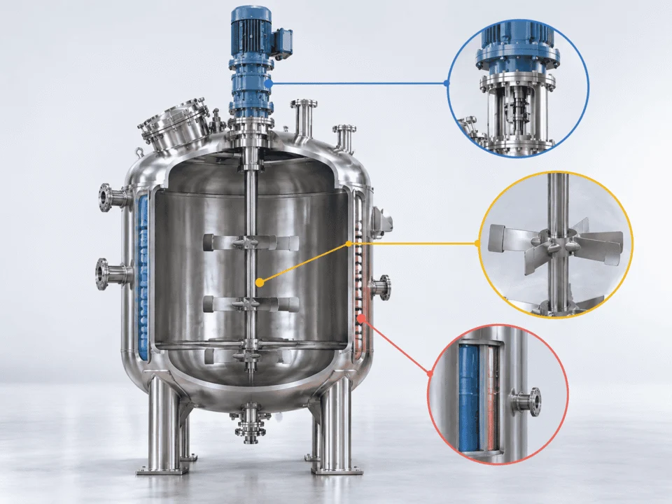
Mixing uniformity, suspension, heat transfer and equipment reliability should be evaluated together.
Impeller Type Is Only One Part of the Mixing System
Impeller geometry should be selected together with shaft length, diameter, speed, number of stages, baffle arrangement and the process condition across the full batch.

For tall vessels or wide operating levels, one impeller stage may not provide enough circulation through the full liquid column.
Do not size the agitator from RPM alone.
Tall liquid columns may need multiple stages to maintain circulation through the full vessel.
Baffle design can suppress vortexing and redirect rotational flow into useful circulation.
Initial, maximum and final viscosity may require the drive system to handle very different loads.
Most Agitator Problems Start Before Fabrication
Poor mixing performance is often caused by an incomplete process definition, not by one isolated component. The vessel, agitator, seal and thermal system should be checked together before the design is released for fabrication.
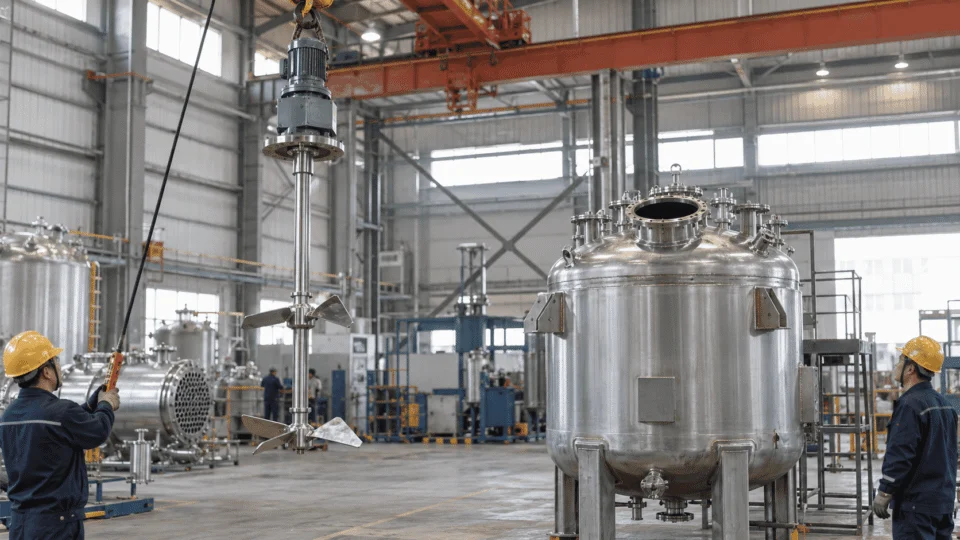
Confirm the agitator envelope, shaft loading, nozzle orientation, minimum working level and internal clearances before the vessel is released to production.
RPM does not show torque, flow pattern, tip speed or power demand.
Review duty, viscosity, impeller diameter, power and torque together.
Motor power can be meaningless if the required mixing objective is still unclear.
Define blending, suspension, dispersion, heat-transfer or shear duty first.
Polymerization, concentration or cooling can change viscosity dramatically.
Provide initial, maximum and final viscosity whenever the batch changes.
An upper impeller may become partially exposed or lose useful circulation.
Verify impeller immersion at both minimum and maximum batch levels.
Late internals can block circulation or enter the mechanical shaft envelope.
Coordinate internals, nozzles, P&ID and agitator layout before fabrication.
Temperature, fluid compatibility, shaft movement and leakage requirement also matter.
Define the complete seal duty before choosing the seal arrangement.
Tip speed, power per volume, circulation and shaft loading change with scale.
Define which scale-up criterion matters for the process before resizing.
Shaft deflection, critical speed, coupling alignment and dynamic loads should be checked before vibration becomes a field problem.
For non-reactive blending duties, compare Mixing Tanks. For corrosion and material-selection considerations, see Material Selection.
The Reactor Design Is Only as Good as the Fabrication Behind It
Material control, welding quality, dimensional accuracy, pressure testing and final documentation should be planned as part of the reactor package—not added after fabrication is complete.
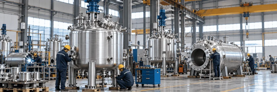
Material Verification
Base material, wetted parts and special alloys should match the process medium, corrosion risk and cleaning requirement.
Welding & Assembly
Shell, heads, nozzles, jacket, supports and agitator mounting features should be assembled with dimensional control and process-specific weld requirements.
Inspection & Testing
The final inspection plan depends on the design code, service condition, customer specification and any required nondestructive examination.
Final Project Dossier
Documentation should match the agreed project scope so the reactor can be installed, inspected and maintained with a clear record of the supplied configuration.
Different destination markets can require different design, conformity-assessment and documentation paths.
Agitated Reactors for Different Process Conditions
The vessel geometry, agitator, seal and thermal system should change with the process—not just the industry name. Typical applications range from low-viscosity blending to solids suspension, gas dispersion and high-viscosity reaction service.

Reaction, neutralization, blending and batch processing
Chemical service can require corrosion-resistant materials, pressure capability, controlled heat transfer and agitation selected around viscosity and reaction behavior.
Chemical Industry →
Controlled batch processing
Material compatibility, cleanability, sealing and process control can become primary design inputs.
Pharmaceutical Industry →
Blending, heating and formulation
Hygienic details, product shear sensitivity and temperature response can influence the reactor configuration.
Food & Beverage →
Pressure, temperature and containment driven service
Process pressure, temperature, hazardous-area requirements and seal duty often become major design considerations.
Petrochemical Industry →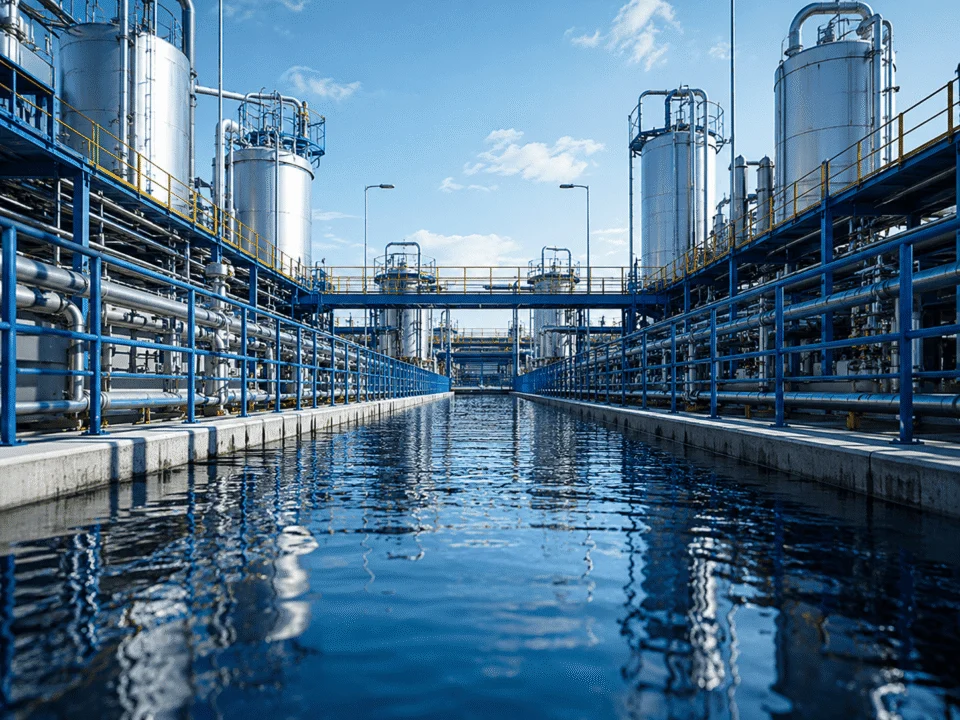
Chemical preparation and treatment processes
Agitation may be used for reagent preparation, solids management, pH adjustment and other treatment duties.
Water Treatment →
Engineered around the actual batch
When the process does not fit a standard application category, start from fluid properties, mixing duty and thermal requirements.
Discuss Your Process →Send the Process Duty Before You Send the Motor Size
Share the working volume, viscosity range, solids or gas conditions, operating pressure, operating temperature and required mixing objective. We can review the reactor, agitator, seal and thermal system together.