
ChannelVessel Intelligent Equipment Co., Ltd. Contact Us
CUSTOM LIQUID STORAGE & TRANSFER

Storage Skid Systems for Liquid Storage & Transfer

Bring liquid storage, refill and transfer together in one coordinated package. ChannelVessel configures tanks, pumps, piping, valves, instrumentation and controls around your usable inventory, delivery duty and site connections.

500–30,000 L Reference tank capacity
CS / SS304 / SS316L Wetted material options
Single / Dual / Multi-Tank Flexible storage layouts

Larger storage requirements can be reviewed with larger vessels, multiple tanks or separate tank-and-transfer modules.
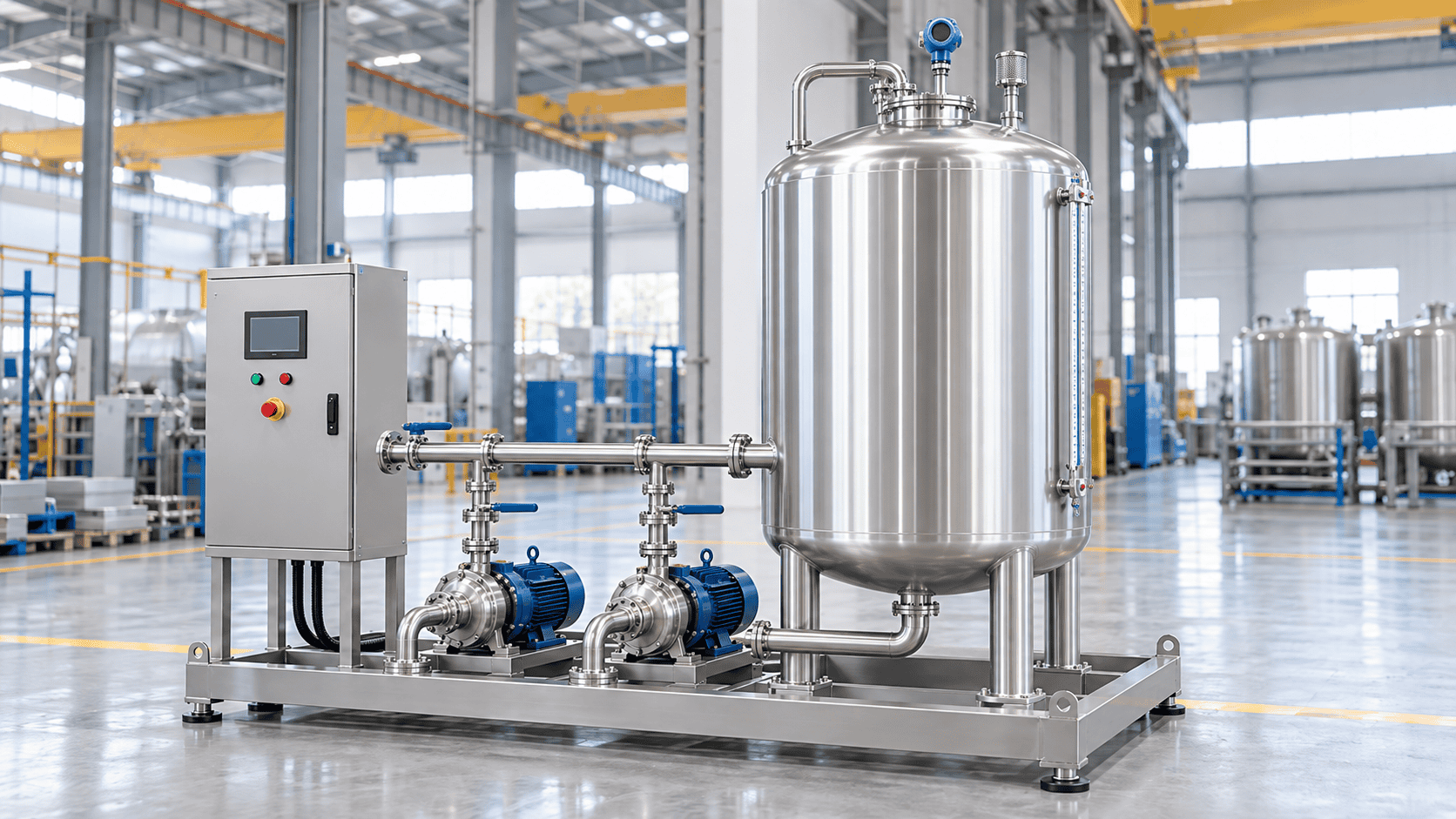
Storage skid system with stainless steel tank, transfer pumps, piping and control panel
ENGINEERED AROUND Usable Inventory + Transfer Duty
CONFIGURATION FIRST

Choose the Right Storage and Transfer Configuration

Start with the operating task, then choose the equipment. Define whether the system must absorb uneven demand, supply a day tank, circulate stored liquid or keep different batches separate.

BUFFER STORAGE

Absorb the difference between supply and demand

Use a buffer arrangement when incoming supply and downstream consumption do not follow the same pattern. Define the largest expected inventory shortfall, the time available to recover it and the conditions under which the receiving process can pause.

CHECK BEFORE SELECTING Required usable inventory, refill availability and downstream demand profile.
ONE TANK OR TWO?

Choose redundancy for a reason, not by habit

Refill while supplying the same liquid

One tank can be considered when inlet, outlet, level-control and product-quality conditions allow simultaneous operation.

Hold an incoming batch pending release

Review separate tanks and controlled transfer paths when the incoming batch must remain isolated before use.

Clean or maintain one tank without losing supply

Check the remaining tank’s usable inventory, isolation and changeover arrangement before calling the system redundant.

Keep different or incompatible products separate

Review tanks, shared piping, valves and cleaning boundaries together rather than separating only the vessels.

Common-point check: Two tanks sharing one pump, one power supply or one unavailable outlet still have a common point that can interrupt delivery.
Need the vessel only, without integrated transfer equipment? Explore standalone storage tanks
SYSTEM SCOPE

What Is Included in a Storage Skid System?

A storage skid coordinates the receiving connection, stored inventory and delivery equipment as one operating package. The tank provides the inventory; the surrounding equipment determines how it is replenished, monitored and supplied to the process.

REFILL SOURCE Road tanker, IBC, bulk tank or upstream process
→
INLET Receiving connection and refill control
→
STORAGE Tank, level monitoring and venting provisions
→
TRANSFER Pump, valves, pressure and flow functions
→
PROCESS Defined outlet and downstream interface
Storage skid system relationship diagram with storage tank, parallel transfer pumps, piping and control panel
SYSTEM RELATIONSHIP Refill Source → Tank → Pump → Instruments → Process

Final arrangement is configured around the required storage and transfer duty.

RECEIVING & STORAGE

Define how liquid enters the system

Identify whether the refill source is a road tanker, IBC, drum, bulk tank or upstream process, and confirm who provides the refill pressure and flow. The skid can receive liquid from existing equipment or include its own unloading pump when required.

The storage vessel is then configured with the required capacity, supports, process connections, level measurement and venting provisions.

TRANSFER & DISTRIBUTION

Size the delivery path around the real duty

Develop the transfer path around required flow and delivery pressure. The package can include a transfer pump, isolation valves, applicable non-return protection, flow or pressure measurement and connections to one or more users.

Recirculation and drainage paths should be reviewed separately from the normal delivery route so their purpose and operating conditions remain clear.

MONITORING & CONTROL

Specify functions, not just hardware

Define local operation, automatic refill requests, pump permissions, alarms and remote signals together. A control panel should be specified by the functions it must perform, not simply by the presence of a PLC or touchscreen.

Filtration, standby pumps, heating, cooling, cleaning connections and containment are selected options rather than assumed standard inclusions.
DESIGN BASIS

Storage Skid Specifications and Design Options

Use these options to define the quotation basis. The final proposal identifies the selected equipment, operating conditions, included features and site responsibilities.

REFERENCE CAPACITY 0.5–30 m³ per tank

Larger storage requirements can be reviewed with a larger vessel, multiple tanks or separate storage and transfer modules.

Do not combine unlike design values. Tank design pressure and pump discharge pressure are separate specification items and should be stated independently.
STORAGE Tank and inventory basis
Reference gross tank capacity 500–30,000 L per tank
Larger storage requirements Larger vessel, multiple tanks or separate modules
Tank arrangement Single, dual or multiple tanks
Tank orientation Vertical or horizontal, according to layout and service
Usable inventory Defined between normal upper inventory and minimum operating inventory
MATERIALS & CONSTRUCTION Wetted and structural options
Wetted materials Carbon steel, SS304 or SS316L; other materials after compatibility review
Construction options Single-wall, double-wall, insulated or jacketed, as applicable
Storage conditions Primarily atmospheric service; pressure and vacuum cases separately defined
Connections Flanged, threaded or appropriate hygienic connections
Design temperature & wall thickness Established from agreed design conditions and calculations
TRANSFER & CONTROL Pump, instrumentation and automation
Pump arrangement Single transfer, duty/standby, recirculation or unloading/refill service
Pump selection Required flow, differential head, fluid properties and suction conditions
Instrumentation Level, pressure, temperature, flow and leak detection according to scope
Controls Manual, local relay control or PLC/HMI functions as specified
Electrical supply Project voltage, frequency, site environment and interface requirements
PROJECT DELIVERY Testing and documentation
Temperature conditioning Insulation, heating, cooling or a specified circulation loop when required
Inspection Agreed inspection plan and shop verification scope
Factory testing Applicable FAT scope agreed before fabrication
Documents GA, P&ID, BOM, operating information and agreed inspection records
STARTING CAPACITY POINTS
500 L 1,000 L 2,000 L 5,000 L 10,000 L 15,000 L 20,000 L 30,000 L

These are inquiry starting points, not a catalogue of interchangeable standard models. Specify capacity as gross volume, usable inventory or required supply time.

USABLE INVENTORY

Calculate Usable Storage and Supply Autonomy

The useful sizing question is not only “How large is the tank?” It is “How much liquid can the process draw before the system reaches its minimum operating inventory?”

CONSTANT-WITHDRAWAL BASIS Required usable inventory = Process demand × Required supply time

This relationship is a starting point for sizing when there is no incoming supply during the required autonomy period.

17 m³ Normal upper inventory
14 m³ Usable inventory
3 m³ Minimum operating inventory
20 m³ WORKED EXAMPLE Gross volume is not the same as usable inventory.

This diagram uses illustrative inventory limits for calculation. Final operating and protection settings are project-specific.

WORKED EXAMPLE

How long can a 20 m³ tank supply the process?

Assume a gross volume of 20 m³, a normal upper inventory of 17 m³ and a minimum operating inventory of 3 m³.

USABLE INVENTORY 17 − 3 = 14 m³
PROCESS DEMAND 1.5 m³/h
THEORETICAL SUPPLY TIME 14 ÷ 1.5 = 9.33 h

Starting from the normal upper inventory with no refill, that is approximately 9 hours 20 minutes of theoretical supply within this assumed operating window.

START FROM THE ACTUAL INVENTORY

If the tank currently contains 8 m³, only 5 m³ remains above the 3 m³ minimum. At 1.5 m³/h, that is approximately 3 hours 20 minutes of supply.

REFERENCE SIZING MATRIX

Translate demand and autonomy into a starting tank volume

The matrix assumes an illustrative operating window from 15% to 85% of gross volume, giving a usable fraction of 70%. These are inventory fractions, not alarm settings or percentages of tank height.

Process demandSupply time without refillRequired usable inventoryCalculated gross volume at 70% usable fraction
0.5 m³/h4 h2 m³2.86 m³
0.5 m³/h8 h4 m³5.71 m³
1.0 m³/h8 h8 m³11.43 m³
1.5 m³/h8 h12 m³17.14 m³
2.0 m³/h12 h24 m³34.29 m³

Calculated volumes are engineering starting points rather than selected tank models. Normal filling limits, alarm levels and overflow protection should remain distinct when the final level schedule is defined.

Review HSE tank-storage guidance
REFILL & TRANSFER DUTY

Match Refill Rate, Pump Duty and Inventory Recovery

Adequate tank volume does not guarantee that inventory can recover fast enough. Check replenishment while the process is still consuming liquid, then verify the transfer pump at the real delivery condition.

NET REFILL RATE Refill flow − Simultaneous process demand
RECOVERY TIME Volume to restore ÷ Net refill rate
WORKED CONDITION

How quickly can the tank recover 14 m³ of inventory?

Assume the process continues consuming 1.5 m³/h while the system refills. The table shows why refill flow must be compared against simultaneous demand rather than considered on its own.

REFILL 1.0 m³/h
NET RATE −0.5 m³/h

Inventory continues falling. The source cannot keep pace with demand.

REFILL 1.5 m³/h
NET RATE 0 m³/h

The current inventory is maintained, but no storage margin is recovered.

REFILL 3.0 m³/h
NET RATE 1.5 m³/h

Restoring 14 m³ takes approximately 9.33 hours.

REFILL 6.0 m³/h
NET RATE 4.5 m³/h

Restoring 14 m³ takes approximately 3.11 hours.

CHECK DELIVERY AT THE LOWEST WORKING INVENTORY

Do not select the pump from tank capacity alone

FLOW Required normal and peak delivery rate
PRESSURE Downstream pressure plus pipe and fitting losses
FLUID Density, viscosity, temperature and vapor-pressure effects
SUCTION Minimum tank inventory, pipe losses and available NPSH

A high published maximum-flow value does not prove that a pump will operate correctly at the installation duty. Suction conditions should be reviewed at the lowest permitted inventory, where available NPSH may be less favorable.

Review Grundfos guidance on NPSH and suction conditions
DUTY / STANDBY LOGIC

A second pump does not remove every common failure point

Define the start permission and changeover logic for a standby pump. A low tank level, blocked common suction path, unavailable power source or closed outlet can affect both pumps.

Normal duty Selected pump meets the required flow and pressure.
Pump fault Standby start occurs only when its operating permissions remain valid.
Source unavailable Do not treat automatic pump changeover as a solution to an empty or isolated source.
Need controlled chemical metering rather than bulk liquid transfer? Explore chemical dosing skids
WETTED MATERIALS

Select Wetted Materials and Temperature-Control Options

Start with the liquid, concentration, temperature and impurities, then review the complete wetted path. A tank material alone does not establish compatibility for pumps, valves, seals, gaskets and instruments.

TANK Shell, heads, nozzles and internal wetted surfaces
PIPING Pipe, fittings, flanges and drain or recirculation paths
PUMP Casing, impeller, shaft and mechanical-seal wetted components
VALVES Body, trim, seats and elastomers
INSTRUMENTS Process connections, diaphragms and wetted sensing elements
SEALS & GASKETS Compatibility with process liquid, cleaning agents and temperature
Carbon steel, SS304 and SS316L are configuration options, not a universal suitability ranking.

Corrosion behavior changes with concentration, contaminants and temperature. Review the actual chemical environment rather than selecting material from the liquid name alone.

Review Outokumpu corrosion guidance
Stainless steel storage tank outlet, piping, valves and transfer pump wetted components
INSULATION

Control heat gain or loss during storage

Define the allowable temperature change and holding period. Insulation reduces heat transfer but does not actively heat or cool the product.

HEATING / COOLING

Specify the target, not just “jacket required”

Provide incoming and target temperatures, required conditioning time and available utilities so the required heat-transfer duty can be reviewed.

RECIRCULATION

Define what the loop must accomplish

State whether circulation is intended for temperature conditioning, filtration or another function. A return line alone does not guarantee complete mixing.

HYGIENIC SERVICE

Treat cleanability as a complete system requirement

Product-contact finish, drainability, connection type, cleaning method and required records should cover the tank, pump, valves and pipework together.

CONTROL & PROTECTION

Level Control, Overfill Protection and Tank Venting

Define normal operating control separately from protective action. The control philosophy should state when filling starts and stops, when transfer is permitted, how abnormal conditions are detected and what must happen before restart.

EXAMPLE CAUSE-AND-EFFECT SCHEDULE

Define the condition, then define the required response

This is a discussion example rather than final PLC logic. Final actions, independence, timing, valve positions and reset requirements should follow the project risk review.

LOW INVENTORY Refill request

Request replenishment after confirming source availability and receiving capacity.

NORMAL REFILL TARGET Stop normal filling

Use the intended process-control function rather than relying on a high-level alarm as the normal stopping point.

LOW-LOW INVENTORY Protect transfer equipment

Remove the pump permission or perform the specified protective action when the minimum operating condition is exceeded.

HIGH LEVEL Abnormal-level warning

Warn that the normal refill range has been exceeded and initiate the defined operator or automatic response.

HIGH-HIGH PROTECTION Execute reviewed inlet shutdown

Stop incoming transfer or perform another approved protective action according to the hazard review and site philosophy.

PUMP FAULT Alarm / conditional standby start

Start a configured standby pump only when its source, suction path and downstream permissions remain valid.

LEAK DETECTED Alarm and defined response

Apply the required action for the affected equipment and containment arrangement rather than assuming one universal shutdown response.

EMERGENCY STOP / POWER LOSS Move to the defined safe state

Stop or isolate equipment as required while preserving any relief, venting or other safety functions that must remain available.
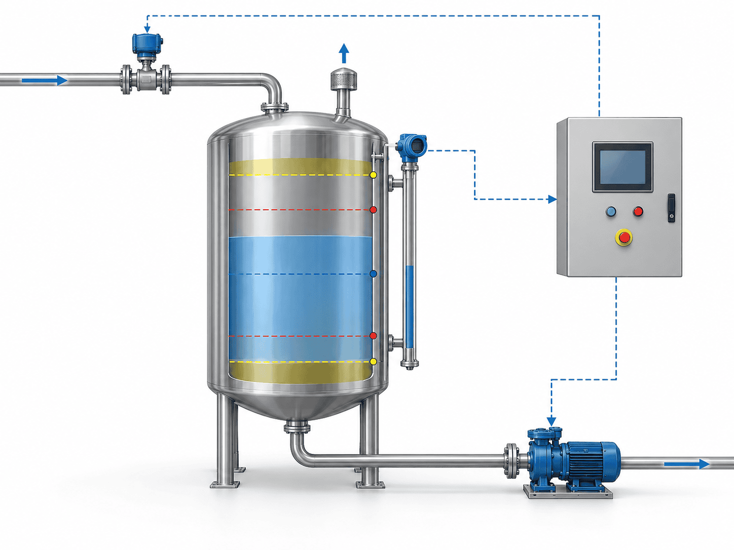
Storage tank level monitoring, inlet control and transfer pump protection diagram
RESPONSE-TIME EXAMPLE

Liquid can continue entering after a high-high condition is detected

Assume a maximum inlet flow of 6 m³/h and 20 seconds from detection to complete cessation of inflow. Conservatively ignore simultaneous outflow.

CONTINUED INFLOW 6 × 20 ÷ 3,600 = 0.0333 m³ ≈ 33.3 L

The 33.3 L result is only the liquid arriving during the assumed response period. It is not the required final reserve and should not be used directly as an alarm-setting value.

VENTING REVIEW

Include filling, withdrawal, thermal effects and applicable emergency cases

Confirm the vent discharge destination and any connection to vapor recovery or treatment. A venting reference does not mean every storage skid is designed or certified to the same code.

LEAK MANAGEMENT

Secondary Containment, Leak Detection and Drainage

Specify the release scenario before choosing a drip tray, double-wall tank or site bund. These features do not describe the same level of protection and should not be treated as interchangeable.

LOCAL COLLECTION Drip Collection

Define the small leaks, maintenance drips or connection points the tray is intended to collect. A local tray does not automatically provide full-volume secondary containment.

CHECK Covered leak points, usable volume and drainage method
TANK BARRIER Double-Wall Construction

Confirm the outer barrier, interstitial monitoring method and which nozzles, pumps or external components remain outside that secondary barrier.

CHECK Interstitial monitoring and components outside the outer wall
AREA CONTAINMENT Integral or Site Bund

Define the equipment inside the containment boundary, effective capacity, material compatibility and the controlled route for recovered liquid.
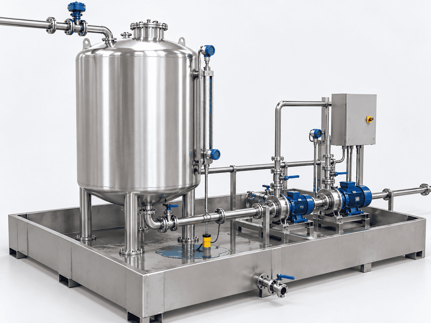
CHECK Effective capacity, displacement, rainfall allowance and recovery route
Storage skid secondary containment with tank, pumps, leak detection and controlled drainage
DEFINE THE BOUNDARY

Know what is inside the protected area and where released liquid can go

Effective containment volume is not simply the geometric size of the tray or bund. Review vessel and equipment displacement, accumulated liquid, drainage controls and any precipitation allowance required by the project basis.

WHAT IS CONTAINED? Tank only, or tank plus pumps, valves and unloading connections?
HOW IS A LEAK DETECTED? Visual inspection, local switch, interstitial monitoring or another defined method?
WHERE DOES LIQUID GO? Controlled recovery, closed drain, waste collection or another approved destination?
WHO PROVIDES THE BUND? Integrated skid scope or site civil works?
Do not apply a generic “110% rule” to every liquid and jurisdiction.

For applicable US oil-storage installations under SPCC, EPA guidance addresses containment for the largest single container plus adequate precipitation freeboard. Other liquids and jurisdictions require their own project basis.

LAYOUT & SITE INTERFACES

Plan Skid Layout, Transport and Site Interfaces

Confirm the installation envelope before fixing the frame. Equipment footprint, maintenance access, transport limits and site tie-ins should be reviewed together rather than treated as separate decisions.
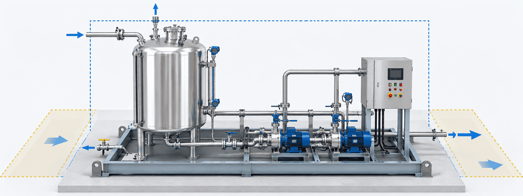
Storage skid layout showing tank, transfer pumps, control panel, package boundary and maintenance access
ONE INTEGRATED SKID OR SEPARATE MODULES?

Capacity alone should not decide the transport arrangement

Compare packed dimensions, transport route, lifting condition, maintenance access and site restrictions for an integrated tank-and-pump skid against a separate tank and transfer module.

A 30 m³ tank is not a universal dividing line. The practical layout depends on vessel geometry, total transport weight, local road limits, lifting access and the amount of equipment installed around the vessel.

INTEGRATED SKID Fewer site connections and more factory integration

Useful when the assembled package remains transportable and maintainable as one unit.

SEPARATE MODULES More flexibility for larger tanks and constrained access

Requires clear responsibility for site piping, cabling, supports and final assembly.

OPERATING MASS EXAMPLE

Check liquid mass, not only the empty equipment weight

Using the earlier worked example, assume a normal upper inventory of 17 m³ and a liquid density of 1,200 kg/m³.

LIQUID MASS 17 × 1,200 = 20,400 kg 20.4 tonnes
This excludes the tank, frame, pumps and pipework. It is an illustrative liquid mass, not a final foundation design load.
SITE INTERFACE REGISTER

Show where the skid supply ends and the site work begins

Interface Information to agree
Liquid inlet and outlet

Connection size and type, location, flow, pressure and supply responsibility.

Vent / vapor recovery

Required destination, connection conditions and site tie-in scope.

Drainage / containment

Recovery route, discharge control and responsible party.

Electrical supply

Voltage, frequency, isolator, incoming cable and earthing scope.

Controls / communications

Required signals, communication method and commissioning responsibility.

Utilities

Heating, cooling or instrument-air conditions where applicable.

Civil / mechanical works

Foundation, anchors, access, offloading and interconnecting pipework.

For split arrangements: include the connecting pipework, supports, cables and site assembly responsibility in the quotation review.
Need several modules or more complex process integration? Explore custom process skids
FAT & DOCUMENTATION

Factory Acceptance Testing and Project Documentation

Define acceptance before fabrication. The inspection and test plan should identify what will be checked, the acceptance criteria, the required records and any purchaser or third-party witness points.

ACCEPTANCE MATRIX Verification should produce evidence, not just a checklist
MATERIALS & FABRICATION Material identification, fabrication checks and traceability

Agree the applicable records and traceability level before manufacturing starts.

DIMENSIONS & ASSEMBLY Main dimensions, connections, supports and installed components

Check the assembled package against the approved arrangement and interface requirements.

TANK & PIPEWORK INTEGRITY Applicable test procedure, boundaries and acceptance criteria

Define the test medium, test scope and required reports rather than applying one universal test pressure.

INSTRUMENTS & SIGNALS Signal identification, indication, scaling and agreed records

Confirm which instruments are checked individually and which functions are demonstrated as part of the assembled system.

CONTROL FUNCTIONS Alarms, permissions, shutdowns and changeover logic

Use simulation where appropriate, but distinguish a simulated signal from a complete end-to-end functional test.

PUMPS & FLOW PATHS Test medium, operating conditions and valve lineup

Record what the factory test proves and what still depends on actual process liquid or site conditions.

SHIPMENT RELEASE Outstanding items, preservation and release records

Close agreed punch-list items or document their disposition before shipment authorization.
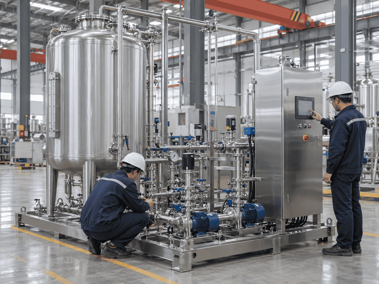
Factory acceptance testing of an assembled storage skid with engineers checking controls, pumps and piping
WHAT DOES THE FACTORY TEST ACTUALLY PROVE?

State the test medium, test conditions and remaining site checks

Water test vs. process liquid

When water is used in the factory, identify which hydraulic or functional results transfer directly and which actual-service conditions still need engineering confirmation.

Simulated signal vs. full loop

A simulated input can verify control logic without proving the installed sensor, field wiring and final element as one complete loop.

Factory interface vs. site interface

External pumps, site valves, utilities or plant control systems may only be fully verified after the skid is connected at site.

PROJECT DOCUMENT PACKAGE

Agree the records required with the equipment

The final package should reflect the purchased scope and agreed inspection requirements rather than a generic stack of documents.

General arrangement drawings
P&ID
Equipment and component lists
Connection schedules
Electrical drawings
I/O list
Control description
Operating & maintenance information
Agreed inspection / test records
Hygienic qualification documents and additional validation support should be specified separately. FAT does not replace every site acceptance and commissioning check.
Need more detail on verification methods and inspection planning? Read our inspection & testing guidance
COMPARE LIKE WITH LIKE

Compare Storage Skid Quotes, Cost Drivers and Lead Time

Two quotations can describe the same nominal tank capacity while covering very different usable inventory, pump duty, controls, testing and site work. Compare the operating duty and supply boundary before comparing the price.

THE KEY QUESTION Are both suppliers pricing the same storage duty, transfer duty and acceptance scope?
Request a Storage Skid Quote
QUOTE AUDIT What should be checked before you compare the total price?
CAPACITY Gross volume or usable inventory?

Confirm whether the quoted tank volume represents gross vessel capacity or the inventory available between normal upper and minimum operating levels.

WETTED MATERIALS Is the complete wetted path identified?

Compare the tank, pipework, pump internals, valve trim, seals and gaskets rather than checking the vessel material alone.

TRANSFER DUTY Is the flow quoted at the required delivery condition?

A pump model or maximum-flow figure is not enough. Check the required flow, outlet pressure, fluid condition and suction basis.

PUMP ARRANGEMENT Which pumps are actually included?

Identify transfer, standby, recirculation and unloading duties separately so optional equipment does not disappear into a generic “pump package.”

CONTROL & PROTECTION Which functions are included in the control scope?

Compare normal refill control, alarms, pump permissions, protective actions, remote signals and the interfaces to external equipment.

CONTAINMENT What release scenario does the quoted arrangement address?

A drip tray, double-wall vessel and full secondary containment are not equivalent. Confirm effective volume, monitored equipment and drainage responsibility.

TESTING & RECORDS What evidence is included at release?

Compare the inspection plan, FAT scope, witness points, test reports and document package rather than accepting “factory tested” as a complete definition.

SITE BOUNDARY Who supplies the work outside the skid?

Clarify foundations, offloading, anchors, interconnecting pipework, power cables, utilities, commissioning and site control-system integration.

COST DRIVERS

What usually changes the quotation value?

Vessel size and design conditions, material selection, pump arrangement, containment, temperature conditioning, electrical requirements, inspection scope, specialist instruments and site services can all change the equipment cost.

Ask optional items to be identified separately so you can see what is changing the price.
LEAD-TIME DRIVERS

What usually changes the delivery schedule?

Drawing approval, vessel fabrication, purchased pumps and instruments, control-panel build, inspection requirements and shipment-release activities may each affect the schedule.

Confirm whether the quoted lead time starts from order placement, drawing approval or another agreed milestone.
A useful quotation shows what is included, what is excluded, what remains to be confirmed and what can change the schedule. Discuss your project scope
BUYER QUESTIONS

Storage Skid Systems FAQs

These questions focus on the decisions that most often change storage capacity, system configuration, supply scope and quotation accuracy.

QUICK CHECK Know the duty before you compare the hardware.

Usable inventory, refill availability, transfer performance and site interfaces usually matter more than the nominal tank capacity alone.

STORAGE How much usable inventory is actually required?
TRANSFER What flow and delivery pressure must be maintained?
SITE What interfaces and responsibilities sit outside the skid?
How is a storage skid different from a standalone storage tank?

A standalone tank provides the vessel and its specified fittings. A storage skid coordinates that vessel with transfer equipment, piping, valves, instruments and controls within an agreed package. The important distinction is the included operating function and supply boundary, not simply whether the tank stands on a steel frame.

How much of the tank capacity is usable?

Usable inventory is the volume between the normal upper operating inventory and the minimum operating inventory. It is not automatically the full gross capacity. In the illustrative 20 m³ example on this page, limits of 17 m³ and 3 m³ provide 14 m³ of usable inventory. Actual limits are project-specific.

Review the storage sizing example
Can a storage skid refill while supplying the process?

Yes, when the receiving and delivery arrangement permits simultaneous operation and the product conditions allow it. Inventory increases only when refill flow exceeds simultaneous withdrawal. Equal flows maintain the current inventory; a lower refill flow leaves the tank drawing down.

Review the refill recovery calculation
When is a dual-tank arrangement necessary?

Consider separate tanks when batches must remain isolated, one vessel needs cleaning while another supplies the process, or different products require separate storage. Continuous demand alone does not automatically require two tanks. Shared pumps, power and transfer paths should also be checked.

Can an existing tank be connected to a new transfer skid?

An existing tank can be considered after reviewing its condition, materials, connections, venting, design limits and available level information. The review should also include pump location, suction piping and site control interfaces. Nominal tank capacity alone is not enough.

Is secondary containment included with the skid?

It should be stated explicitly in the quotation. The scope may use integral containment, an agreed double-wall arrangement, local drip collection or a connection to site-provided containment. These are not interchangeable, so the required release scenario and effective volume should be defined.

Review the containment section
Can the system be supplied for hygienic or pressure service?

These duties can be reviewed as separately specified configurations. Hygienic service requires defined product-contact, drainability, cleaning and documentation requirements. Pressure or vacuum service requires the corresponding design basis, component ratings and applicable conformity scope.

What information is needed for a storage skid quotation?

Start with the liquid, required usable inventory or supply time, delivery flow, available refill source and installation country. Add temperatures, composition, density, viscosity, outlet pressure, space restrictions, utilities and project requirements where known. A drawing is helpful but not required for an initial discussion.

PROJECT INQUIRY

Discuss Your Storage and Transfer Requirements

Tell us what you need to store, how the liquid arrives and where it must go. ChannelVessel can review the tank arrangement, usable inventory, transfer duty, controls and site interfaces together before the equipment scope is finalized.

LIQUID / PRODUCT Name, concentration and available safety data

Share the liquid name, concentration and relevant composition information when known.

STORAGE REQUIREMENT Preferred capacity or required hours of supply

If tank size is unknown, provide process consumption and the autonomy time you want to maintain.

TRANSFER REQUIREMENT Normal / peak flow and delivery pressure

Include downstream pressure or equipment duty where this information is already available.

REFILL ARRANGEMENT Source, available refill flow and delivery frequency

Tell us whether liquid arrives from a tanker, IBC, bulk tank or upstream process.

INSTALLATION Country, available space and site conditions

Drawings, utility conditions and site photos can be added later if they are not ready yet.

NOT SURE ABOUT EVERY VALUE? That does not prevent an initial review.

Mark unknown information as “Not sure.” We can start from the operating requirement and identify what still needs to be confirmed before final design.
NEED HELP CHOOSING TANK SIZE? Send your expected consumption and required supply time.
ALREADY HAVE A LAYOUT OR SPECIFICATION? Send it for a coordinated equipment and interface review.
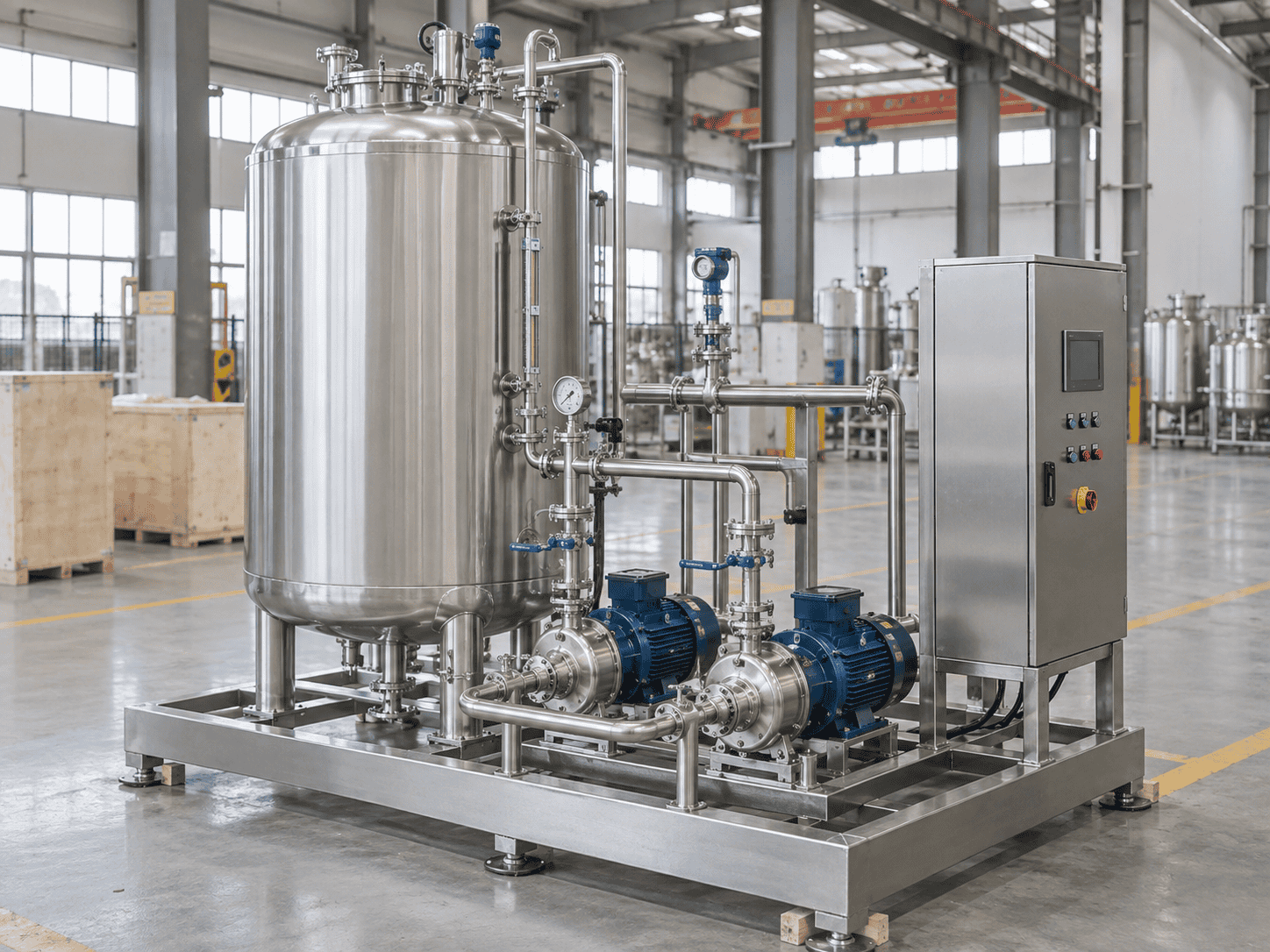
Completed storage skid system with stainless steel tank, twin transfer pumps, piping and control panel in a manufacturing workshop
START WITH THE OPERATING REQUIREMENT Not just a tank volume.

A useful proposal should connect storage capacity, refill behavior, pump duty, controls and site interfaces into one coordinated scope.

Scroll to Top
DRAWING & FILE REVIEW

Send Your Drawings

Upload your drawings, datasheets or existing specifications. Our engineering team will review the files and respond with technical feedback.

Engineering Review

Drawings, specifications and process requirements

Confidential File Handling

Project files are used only for technical review and quotation

Faster Technical Feedback

Clearer inputs help us respond more accurately and efficiently

DRAWING & FILE REVIEW

Send Your Drawings

Upload your drawings, datasheets or specifications. Our engineering team will review your files and provide technical feedback.

Contact Form Demo (#3)
Project Protected NDA available
12h Response
ASME / PED
AFTER SUBMISSION
01 Review
→
02 Confirm
→
03 Quote
TECHNICAL QUOTATION

Get a
Technical Quote

Tell us what you need. Our engineering team will review your requirements and respond within 12 hours.

Engineered for Your Application

From concept to certified manufacturing

Global Compliance

ASME, PED and other international standards

Expert Support

Direct access to our engineering team

TECHNICAL QUOTATION

Get a Technical Quote

Tell us what you need. Our engineering team will review your requirements and respond within 12 hours.

Contact Form Demo
Project Protected NDA available
12h Response
ASME / PED
AFTER SUBMISSION
01 Review
→
02 Confirm
→
03 Quote