
CHANNELVESSEL · EMULSIFICATION TANKS
Emulsification Tanks for Oil–Water Mixing
ChannelVessel supplies custom emulsification tanks that combine a process vessel, bulk agitation and a rotor–stator homogenizer for food, cosmetic and industrial formulations.
Choose a new emulsifying tank, an external homogenizing loop for an existing vessel, or a vacuum-equipped package. Select the arrangement around your product, batch range and required emulsion quality.
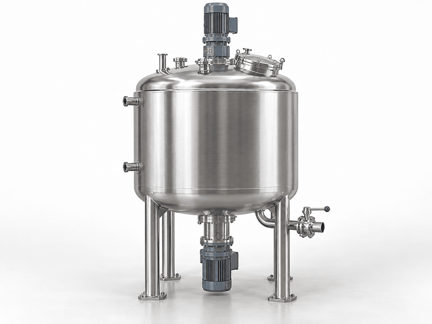
- Capacity choices from 50 to 2,000 L, with other sizes evaluated individually.
- Stainless steel 304 or 316L product-contact options.
- Independently selected bulk-agitator and homogenizer drives.
- Jacketed heating and cooling, selected controls and defined auxiliary equipment.
Start with your product, normal and smallest batches, and the processing problem you want to solve. The proposal can then define the equipment, factory interfaces and acceptance requirements.
PRODUCT APPLICATIONS
Applications and Process Requirements
An emulsification tank disperses one immiscible liquid into another. Identify the continuous phase—water for an oil-in-water emulsion, oil for a water-in-oil emulsion—alongside the phase ratio and addition sequence. The equipment must support the formulation and the changes it undergoes during processing.
Scroll to view all columns.
| Product or formulation | Main processing concern | Configuration to evaluate |
|---|---|---|
| Sauces and dressings | Phase addition, increasing viscosity, air incorporation and product discharge | Controlled feed, rotor–stator homogenization, effective bulk movement and a suitable discharge route |
| Cosmetic lotions and creams | Hot-phase combination, viscosity development during cooling and sensitive late additions | Separate homogenizer and scraper drives, a jacket, temperature control and vacuum where the process requires deaeration |
| Industrial oil–water formulations | Chemical compatibility, required droplet distribution and changing rheology | Compatible wetted materials and seals, a suitable workhead, defined circulation and thermal service |
Powder wetting, hydration, dissolution and deagglomeration are separate duties. A recipe may need several of them, but dissolving sugar or hydrating a thickener does not by itself establish liquid–liquid emulsification performance.
For several products in one tank, identify the smallest charge, the most demanding viscosity stage, the highest temperature and the cleaning changeover. Provide viscosity with its measurement temperature and method; a finished-product value may not describe the conditions during emulsification or cooling.
For general blending or dissolving duties, compare our mixing tanks.
WORKING PRINCIPLE
How an Emulsification Tank Works
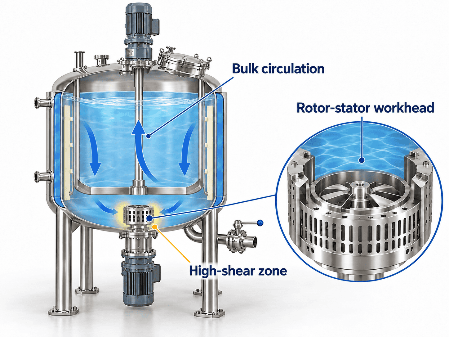
The rotor–stator workhead concentrates shear in a local processing zone. The bulk agitator moves product through the vessel and supplies material to that zone. These duties need separate consideration as viscosity and liquid level change.
An anchor or scraper can support movement near the wall during processing and cooling. Independent drives let the homogenization stage finish while suitable bulk agitation continues for cooling or sensitive ingredient addition.
Choose the Equipment by the Processing Task
Scroll to view all columns.
| Equipment | Main duty | What to establish before selection |
|---|---|---|
| Standard mixing tank | Bulk blending, maintaining uniformity or a defined dissolving duty | Whether the formulation needs an additional droplet-reduction stage |
| High shear emulsification tank | Liquid–liquid emulsification with bulk circulation and local rotor–stator treatment | Workhead suitability, product movement, batch range and measurable quality targets |
| Vacuum emulsifying system | Emulsification with a required deaeration or vacuum-transfer stage | Vacuum duty, vessel design, seals, vapour handling and control functions |
Vacuum addresses a defined process need; it does not replace a suitable formulation, shear device or circulation arrangement.
Why Rotor Speed Alone Is Insufficient
Rotor diameter changes the peripheral speed at the same rpm:
Rotor tip speed (m/s) = π × rotor diameter (m) × rpm ÷ 60.
Scroll to view all columns.
| Hypothetical rotor diameter | Rotational speed | Calculated tip speed |
|---|---|---|
| 75 mm | 3,000 rpm | 11.8 m/s |
| 150 mm | 3,000 rpm | 23.6 m/s |
These calculations illustrate geometry, rather than selected machine ratings. Tip speed is also different from shear rate. Workhead geometry, flow, product rheology and energy input still affect the result, so neither equal rpm nor equal tip speed establishes equivalent emulsification when scaling up.
CONFIGURATION OPTIONS
Emulsification Tank Configurations
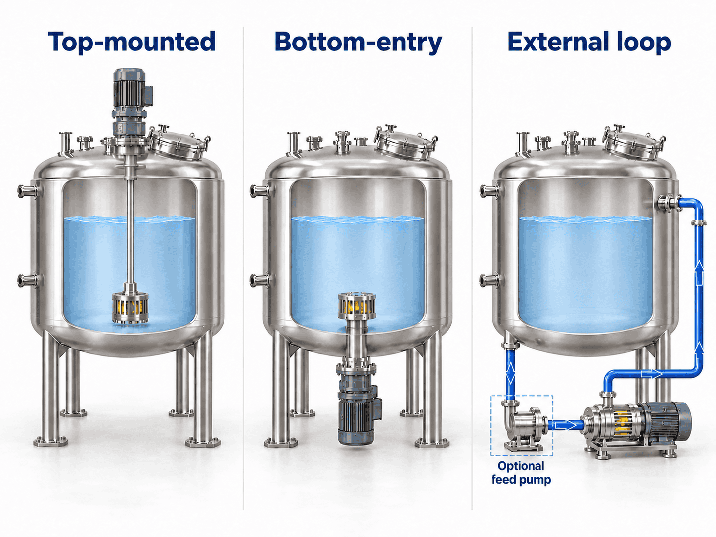
Select the homogenizer position together with the vessel geometry, bulk agitator, batch range and maintenance access.
Top-Mounted In-Tank Homogenizer
A shaft carries the workhead into the batch from above. Evaluate this arrangement for direct in-vessel processing where the head remains immersed and the agitator can maintain useful circulation.
Check the lowest processing level, the position of the head relative to the bulk flow, and overhead space for shaft or workhead removal.
Bottom-Entry Homogenizer
The workhead enters through the vessel bottom. A low-positioned shear zone can be useful where the vessel layout and circulation suit it.
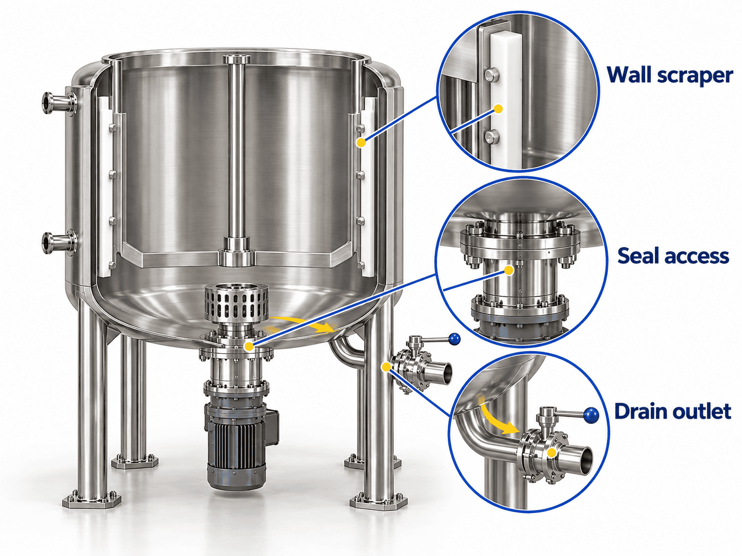
Confirm coverage at the smallest charge, bottom flow, outlet interaction and seal access beneath the vessel. Bottom entry alone does not establish a minimum working volume.
External Recirculation Homogenizer
Product leaves the tank, passes through an inline homogenizer and returns through a defined connection. This is an option for a new installation or an existing vessel.
Select flow against the actual viscosity, temperature and pipe resistance. Identify any feed pump, loop hold-up, return position, drains and cleaning route. A recirculating batch and a continuous once-through process have different feed and acceptance requirements.
Scroll to view all columns.
| Process or installation priority | Starting arrangement to evaluate | Decisive check |
|---|---|---|
| Direct in-vessel treatment with overhead access | Top-mounted homogenizer | Head immersion and circulation across the batch range |
| A low-positioned shear zone | Bottom-entry homogenizer | Minimum-charge coverage, seal service space and drainage |
| Add homogenization to a suitable existing tank | External product loop | Feed and return connections, flow at viscosity, loop cleaning and hold-up |
| Keep a thickening batch moving during cooling | Selected bulk agitator with any suitable shear route | Torque and circulation through the changing viscosity profile |
Understand Recirculation Turnover
Nominal turnovers = actual loop flow × elapsed time ÷ total circulating charge, using consistent units.
If the total circulating charge is 500 L and actual loop flow is 3,000 L/h, 30 minutes represents 3 nominal turnovers. This is cumulative flow equivalent to three charge volumes; it does not prove every droplet passed through the head three times or that the product meets its quality target. Include loop hold-up in the charge basis and confirm flow under processing conditions.
For a retrofit, include a drawing of the existing tank, agitator details and information on the available service space. For a process centered on deaeration, see our vacuum emulsifying mixers.
CAPACITY & TECHNICAL DATA
Capacity and Technical Specifications
Select capacity from the required working batch, minimum charge and complete production cycle. Then match the vessel, bulk agitator, homogenizer and thermal system to that duty.
Configuration and Specification Options
Scroll to view all columns.
| Specification item | Choices or selection basis |
|---|---|
| Capacity classes | 50, 100, 200, 500, 1,000, 1,500 and 2,000 L; other sizes evaluated individually |
| Product-contact construction | Stainless steel 304 or 316L, with the wetted-component boundary stated |
| Bulk agitator | Anchor or scraper arrangement, selected for circulation and required torque |
| Homogenizer route | Top-mounted, bottom-entry or external product recirculation |
| Bulk-agitation speed reference | 0–65 rpm with the selected drive |
| Homogenizer speed references | 0–3,000 or 0–3,600 rpm with the selected drive |
| Motor specification | Separate bulk-agitator and homogenizer ratings, with operating range and duty stated |
| Vessel construction | Single-wall, or jacketed with selected insulation |
| Thermal service | Electric, steam or hot-water heating; cooling interface matched to the temperature profile |
| Vacuum | Optional equipment package with defined vessel and auxiliary design conditions |
| Controls | Button operation or selected PLC/HMI functions; independent drive control and temperature monitoring |
| Factory electrical interface | Destination voltage, frequency, phase and a complete connected-load schedule |
Speed entries describe configuration references; zero denotes stop. The selected motor, gearing, drive and workhead determine permissible continuous operation. A capacity label does not determine a motor rating.
Define Four Different Volumes
Scroll to view all columns.
| Capacity term | Definition to record |
|---|---|
| Gross vessel volume | Total internal volume on the agreed geometric basis |
| Normal working batch | Routine charge under the specified processing conditions |
| Maximum working batch | Highest permitted charge for the selected arrangement and process |
| Minimum working batch | Lowest charge that maintains head coverage, circulation and measurement conditions |
Consider the highest intermediate fill, ingredient additions and foam space. Establish these volumes in the specification rather than applying a universal filling percentage.
Convert mass and volume using density at the relevant temperature. An assumed 500 kg batch at 1.05 kg/L occupies about 476 L, rather than 500 L. Density changes through heating can also affect the operating fill.
Example: Turn a 500 L Requirement into a Process Brief
The following is an illustrative inquiry for a heated lotion. It is a starting specification, with assumed process inputs rather than a tested equipment model.
Scroll to view all columns.
| Inquiry field | Example requirement or proposed configuration |
|---|---|
| Working batch | 500 L normal; 250 L smallest intended charge |
| Product behaviour | Oil-in-water lotion; customer to supply phase ratio and viscosity measurements at emulsification and discharge |
| Product-contact construction | 316L wetted metal, including the specified workhead, valves and product piping |
| Mixing arrangement | Independent scraper agitator and bottom-entry rotor–stator homogenizer |
| Thermal profile | Assumed product heating from 25°C to 75°C, then cooling to 35°C |
| Heating/cooling interface | Hot-water heating and chilled-water cooling; site supply conditions required |
| Controls | PLC/HMI with separate drive settings, temperature display and stage timers |
| Electrical input | Example factory supply: 480 V, 60 Hz, three-phase |
| Items to resolve in the proposal | Gross and maximum volume; head coverage at 250 L; individual motor ratings; thermal duty and utility flow; discharge, cleaning and acceptance scope |
This brief connects vessel selection to the product and factory. Gross volume, motor power and cycle time follow the completed duty review.
Estimate Production from the Complete Cycle
For a hypothetical 500 L working batch, assume 15 minutes for charging, 35 for processing including temperature-control stages, 15 for discharge and 25 for allocated cleaning. The complete cycle is 90 minutes.
Average processed-volume rate = 500 × 60 ÷ 90 ≈ 333 L/h.
This scheduling example assumes the stated stages run sequentially and excludes losses and downtime. It does not establish finished-product yield or an equipment throughput rating.
PROCESS CONTROL
Process Control for Emulsion Quality
Define the required product before setting the processing intensity. Droplet distribution, viscosity, appearance, incorporated air and stability can respond differently to addition, temperature and shear.
Control the Processing Stages
- Prepare the phases. Establish starting temperatures, ingredient preparation and the order of addition.
- Introduce the second phase. Match its addition rate to the available circulation and shear treatment.
- Homogenize. Apply the selected speed and time while maintaining supply to the workhead.
- Cool and complete the recipe. Adjust bulk agitation as viscosity develops and add sensitive ingredients under their established conditions.
- Discharge and clean. Use the defined transfer route and the agreed changeover procedure.
Where selected, PLC/HMI functions can provide separate drive settings, stage timers and temperature control. Specify recipe storage, data recording and operating permissives explicitly if they are required.
Use Product Measurements to Set the Endpoint
A useful process trial compares samples at defined times under consistent sampling and measurement conditions. Use the results to establish the required homogenization stage and subsequent bulk-mixing stages.
Smaller droplets create more interfacial area, which the emulsifier system must support. Continuing to apply shear can therefore fail to improve stability. A satisfactory droplet result also does not establish the required viscosity or storage performance.
Scroll to view all columns.
| Observation | Checks before extending processing | Decision supported |
|---|---|---|
| Droplet distribution stops improving while temperature rises | Formulation, sampling method, workhead, addition history and material supply to the shear zone | Revise the process or shear arrangement before assuming more time will solve the problem |
| The fine fraction is acceptable but a coarse tail remains | Representative sampling, agglomeration, air and vessel circulation | Investigate the source of the coarse result and review Dv90 alongside the distribution |
| Circulation weakens during cooling | Viscosity profile, available agitator torque and loop resistance | Review bulk agitation, flow and discharge at the demanding stage |
| Foam or unwanted air develops | Surface vortex, feed position, liquid level and return location | Adjust addition and circulation; assess a defined deaeration stage if needed |
Record the accepted settings with formulation version, batch size, workhead, addition sequence and temperature history. This creates a usable production reference for later batches.
HEATING & COOLING
Heating, Cooling and Factory Utilities
Specify heating and cooling around the product-temperature profile. Batch mass, heat capacity, starting temperature, required final temperature and available cycle time determine the information needed for thermal selection.
Thermal Configuration
Electric heating can be configured where the available electrical supply and heating duty suit the project. Steam heating requires a defined steam service and suitable jacket controls. A hot-water circuit can be evaluated where its temperature range and transfer capacity match the process.
For cooling, provide the available water or chilled-water temperature, flow and pressure, together with the required product cooling profile. Increasing viscosity can change vessel circulation and heat transfer, so review the batch through its full temperature range.
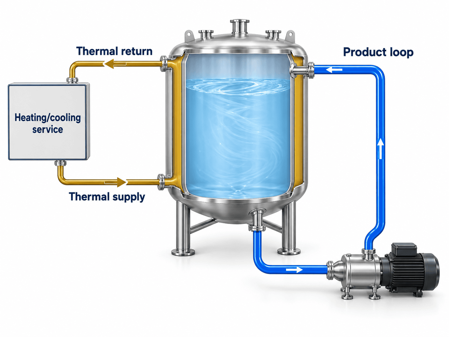
Keep the two circuits clear:
- Product circuit: vessel, homogenizer, any feed pump, product piping and return connection.
- Thermal circuit: jacket, heating or cooling medium, supply, return and temperature-control components.
An external heating or cooling circuit does not by itself provide external product homogenization.
Utility and Layout Requirements
Scroll to view all columns.
| Factory interface | Information needed |
|---|---|
| Electrical supply | Voltage, frequency, phase and available capacity; identify supplies such as 380 V/50 Hz or 480 V/60 Hz when preparing the inquiry |
| Heating service | Electric supply or steam/hot-water conditions, required product temperatures and heating time |
| Cooling service | Supply temperature, flow, pressure and required cooling time |
| Vacuum support | Deaeration or transfer duty, selected pump and any service-water, condensate or vapour-handling requirements |
| Compressed air | Pressure and quality where pneumatic equipment is selected |
| Cleaning and drainage | Cleaning-liquid supply and return, drains and the boundary of any cleaning skid |
Define the main vessel and jacket design conditions separately. Identify gauge or absolute pressure and distinguish operating settings from design limits. Positive-pressure operation or pressure-assisted discharge requires an appropriate vessel specification.
Check motor and drive selection against the actual supply frequency as well as voltage. The quotation should list the bulk-agitator motor, homogenizer motor, electric-heater load and auxiliaries separately, with the required site electrical capacity.
The layout should show the equipment footprint, access around the controls and valves, any raised-cover height, and space for seal, shaft or workhead maintenance. Include the delivery route through doors and other restricted access points.
MATERIALS & CLEANING
Product-Contact Materials, Cleaning and Maintenance
Material selection covers the entire wetted system. Review the formulation, operating temperatures, cleaning chemicals and any ingredients that affect corrosion, wear or elastomer compatibility.
Materials and Wetted Components
Scroll to view all columns.
| Component or requirement | Detail to define |
|---|---|
| Vessel and product-contact metal | Selected 304 or 316L construction and the documented contact-material boundary |
| Homogenizer, valves and product piping | Materials and connections consistent with the process and cleaning requirements |
| Seals and scraper components | Compatibility with ingredients, temperatures, movement and cleaning chemicals |
| Welds and surface treatment | Required finish, treatment, inspection locations and verification method |
| Product discharge | Outlet geometry, transfer method, drainage and access for inspection |
Specify the surface finish as a measurable requirement. For example, an inquiry may request Ra ≤ 0.8 µm on identified wetted metal surfaces, with the finishing process, weld treatment, measurement locations and inspection record agreed in the proposal. This is an example procurement target; the ordered finish and verification scope must be stated.
Surface roughness is only one part of cleanability. Review joints, seals, access and drainage alongside the finish.
Cleaning Access and Serviceability
Review the surfaces around the workhead, shaft, seals, scraper assembly and outlet. Product recirculation adds valves, pump components and piping that also need drainage and cleaning access.
A lifting cover can improve inspection and component access when the layout and mechanical arrangement permit it. A fixed cover needs suitable access through the specified openings. Both arrangements should allow the planned maintenance tasks.
A spray device or cleaning connection is one part of a cleaning system. A complete circuit also needs the required liquid supply, return route, flow, temperature, cleaning chemistry and drainage. If a CIP skid is included, define its tanks, pump, heating and control scope.
Agree on cleaning coverage and residue acceptance for the actual product and procedure. Include access for inspecting the locations most likely to retain material.
PACKAGE & PRICING
Equipment Package and Price Factors
Compare equipment quotations using the same working batch, formulation duty and supply boundary. A tank module, an emulsification package and a system with its own utilities represent different purchase scopes.
Choose a Quotation Boundary
These package definitions help structure an inquiry. The itemized proposal establishes the final inclusions.
Scroll to view all columns.
| Quotation scope | Equipment to request | Interfaces or additional scope to identify |
|---|---|---|
| Tank module | Vessel, selected bulk agitator and homogenizer, drives, seals, outlet and specified jacket | Site heating/cooling, product transfer, controls, cleaning and installation responsibilities |
| Integrated emulsification package | Tank module plus selected product pumps, recirculation piping, valves, instruments and control cabinet | Metered addition, vacuum, cleaning equipment and utility production as separately defined items |
| System with dedicated auxiliaries | Process package plus specifically requested phase-preparation, vacuum, thermal or CIP equipment | Utility capacities, piping boundaries, site connections, commissioning and training |
For each quotation, request the following details:
- Individual motor ratings, electric-heater load and auxiliary loads.
- Product-contact materials, seals, surface finish and included connections.
- Heating and cooling duty, available utility conditions and required supply/return interfaces.
- Selected controls, instruments and any data-recording functions.
- Inspection, documentation, packing, transport and site-service scope.
A steam connection does not include a boiler. A cooling connection does not include a chiller. Likewise, a CIP connection, a cleanable product circuit and a complete CIP skid are different supply items.
What Determines the Price?
The main inputs are vessel size, viscosity, mixing torque, homogenizer route, wetted materials, thermal duty, vacuum, automation and cleaning scope. Recirculation pipework, pumps, inspection requirements and installation services can materially change the delivered cost.
For a comparable quotation, provide the product details, normal and minimum batches, temperature profile, available utilities and required package boundary. ChannelVessel can then evaluate the configuration and prepare an itemized proposal.
INSPECTION & ACCEPTANCE
Inspection, Documentation and Acceptance
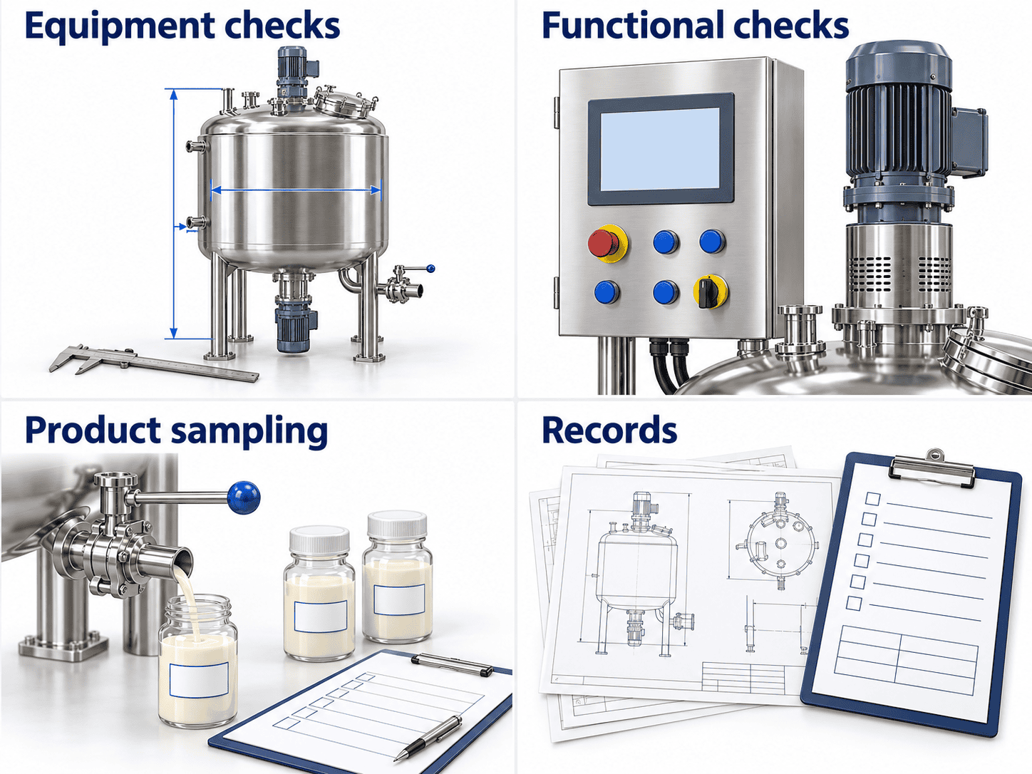
Agree on mechanical inspection, functional testing and product-specific process acceptance as separate parts of the order. A water trial can check selected functions; an emulsion claim requires the relevant formulation and processing conditions.
Equipment Inspection and Records
The ordered inspection plan can cover material identification, vessel dimensions, connections, specified surface finish, seals, drives, instruments and control functions. Define any main-vessel or jacket tests against their respective design specifications.
The document schedule can include approved drawings, material records, operating and maintenance instructions, electrical information and agreed inspection reports. State the required documents and test scope in the proposal and contract.
Build an Acceptance Record Around the Product
Scroll to view all columns.
| Acceptance item | Conditions to define | Record needed |
|---|---|---|
| Droplet distribution | Formula, charge, sample location/time, preparation and measurement method | Distribution plus agreed statistics such as Dv50 and Dv90 |
| Viscosity | Sample temperature, instrument, geometry and speed or shear conditions | Result with the complete method |
| Stability | Storage temperature, duration, container, observations and acceptance limits | Separation, appearance and other agreed property changes |
| Thermal performance and cycle | Charge, utility temperatures/flow and timing boundaries | Product-temperature trace and stage times |
| Air incorporation | Product-specific measurement or agreed observation method | Result and sampling conditions |
| Cleaning | Product, cleaning sequence, inspection locations and residue criteria | Inspection or sampling record |
Dv50 and Dv90 are volume-based percentiles: 50% and 90% of the measured droplet volume respectively lie below those diameters. Report them with the distribution and method, rather than using an undefined “fineness” value.
Example Trial-Record Format
For an illustrative 500 L process trial, an agreed plan could collect samples at 5, 10 and 15 minutes after phase addition is complete. Record the head settings, batch temperature, sample location and measurement preparation at each point.
Scroll to view all columns.
| Sample ID | Elapsed homogenizing time | Batch temperature | Dv50 / Dv90 | Viscosity at the defined test conditions |
|---|---|---|---|---|
| A | 5 min | Record | Measure | Measure |
| B | 10 min | Record | Measure | Measure |
| C | 15 min | Record | Measure | Measure |
The schedule illustrates a test format; it contains no equipment results or universal processing time. Set the actual intervals and pass/fail limits for the product before testing. Where the tank must process 250 L as well as 500 L, define a separate minimum-charge check.
Retain the formulation version, addition history, workhead and relevant flow or drive settings with the results. Confirm storage performance separately: a short observation or accelerated test supports only its defined scope, and shelf-life conclusions need an appropriate study.
Where a product trial is included, agree on ingredients, quantity, location, responsibilities and acceptance criteria in advance.
BUYER QUESTIONS
Emulsification Tank FAQs
How is an emulsification tank different from a standard mixing tank?
It combines bulk circulation with a shear device suited to liquid–liquid emulsification. A general blending tank may provide uniformity without the required droplet-reduction stage. Compare the processing task, workhead and circulation rather than using rpm as the dividing line.
Does every emulsification tank need vacuum?
No. Select vacuum for a defined deaeration or transfer requirement. The package must then address the vessel design, seals, instruments and vacuum-side auxiliaries. Compare our vacuum emulsifying mixer systems when this stage is central to the process.
What is the minimum batch size?
It depends on head coverage, vessel geometry, circulation and the measurement conditions. A 500 L normal batch does not prove that a 50 L charge is workable. State your smallest batch and require its suitability to be checked for the proposed arrangement.
Can an inline homogenizer be added to an existing tank?
It can be evaluated as a retrofit. Send the tank drawing, agitator details and viscosity profile. Review feed and return connections, flow at processing viscosity, any feed pump, loop hold-up, cleaning and service space as one circuit.
Can a rotor–stator tank produce every fine emulsion?
The formulation and target distribution determine the required process. For demanding submicron duties, evaluate high-pressure homogenization or another suitable downstream stage through product testing. The tank may provide phase preparation and premixing; a rotor–stator speed value alone establishes no droplet-size guarantee.
Can one tank handle several products and sensitive ingredients?
Review the batch range, viscosity and temperature profile, material compatibility and changeover for each product. Separate drives allow homogenization and bulk agitation to operate in different stages. Introduce shear-sensitive ingredients under the conditions established for the recipe.
How much does a custom emulsification tank cost?
Price follows the specified duty and supply scope. Compare the same working volume, materials, drives, thermal service, vacuum, automation and auxiliaries. Send your process brief for an itemized quotation that identifies factory interfaces and optional equipment.
Can the equipment match our local power supply?
Provide voltage, frequency, phase and available capacity. The selection must cover the complete package—motors, drives, electric heaters, pumps and controls—and identify destination-specific electrical requirements before manufacture.
PROJECT INQUIRY
Specify Your Emulsification Tank
Tell us about your product, normal and smallest batches and summarize the main processing problem. Send the information you have; identify unknown values so they can be resolved during the equipment review.
Scroll to view all columns.
| Inquiry detail | What helps define the equipment |
|---|---|
| Formulation | Product type, continuous phase, phase ratio and ingredients or compatibility information you can disclose |
| Batch range | Normal and minimum quantities in litres or kilograms, with density where conversion is needed |
| Product properties | Viscosity with method and temperature, solids and changes during heating or cooling |
| Processing stages | Addition sequence, temperature profile, shear-sensitive ingredients and any vacuum stage |
| Quality and acceptance | Required distribution, viscosity, appearance, stability and proposed test methods |
| Factory | Power, heating/cooling utilities, space, destination and existing connections |
| Supply scope | Transfer, cleaning, control, documentation and site-service requirements |
Use the proposal to review the vessel and mixing arrangement, individual drive ratings, thermal and utility requirements, itemized supply boundary, inspection and documents, and any process-trial plan. This provides a basis for your purchasing and engineering teams to compare equipment.