
ChannelVessel Intelligent Equipment Co., Ltd. Contact Us
CUSTOM THERMAL PROCESS SYSTEMS

Heat Exchange Skids for Industrial Heating & Cooling

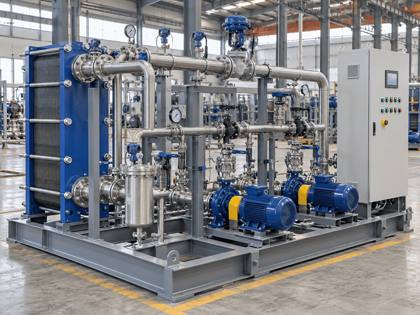
ChannelVessel supplies custom heat exchange skids that integrate heat exchangers, piping, valves, instrumentation and controls into a factory-assembled package. Also called heat exchanger skid packages, these systems can include circulation pumps, insulation and utility-side equipment for industrial heating, cooling and heat recovery.

Tell us what flows through each circuit, the temperatures you need and the utilities available at your site. We build the proposal around those conditions, with the exchanger arrangement, control requirements and connection points clearly defined.
Heating & Cooling Heat Recovery Plate or Shell-and-Tube Integrated Controls
A process description is enough to start. Send the information you have and identify any values that are still unknown.
Custom heat exchange skid package
Custom Thermal Duty
Integrated Pumps & Controls
Defined Site Interfaces
PACKAGE SCOPE

Complete Heat Exchanger Skid Packages—with a Clear Supply Boundary

A complete package starts with a clear agreement about what it includes. ChannelVessel can configure the thermal equipment, circulation, piping and controls around your process, while identifying the connections and services that remain with the plant.

BUYER CHECK Compare quotations at the same connection points.

A lower initial price may reflect missing pumps, control valves, insulation or documentation rather than an equivalent package.

Liquid-to-Liquid Heating & Cooling

Transfer heat between separate process and utility circuits using hot water, cooling water, chilled water or a compatible glycol solution. The package can use existing plant circulation or include dedicated pumps where the hydraulic arrangement requires them.

Steam-to-Liquid Heating

Combine the heat exchanger with steam regulation, instrumentation and a condensate-handling arrangement. Selection considers changing heat demand and condensate return conditions, not only the available steam supply.

Heat Recovery

Recover useful heat from an available stream and transfer it to a receiving process. Define when both streams are available, the required temperatures and the backup heating or cooling arrangement before assigning a recovery duty.

Closed-Loop Temperature Control

Create a circulation package with the required heat exchanger, pump, valves and temperature control. Expansion, pressurization, air removal, filling and draining provisions can be incorporated where the selected loop requires them.

CONFIGURATION

Configuration and Specification Schedule

Exchanger constructionGasketed plate-and-frame, brazed plate, semi-welded plate, fully welded plate or shell-and-tube.
Thermal dutySized from process and utility conditions; calculated duties are project-specific rather than fixed standard capacities.
Flow rateMinimum, normal and maximum flow specified separately for each circuit.
Operating conditionsNormal and expected operating pressures and temperatures on both sides.
Design conditionsDesign pressure and temperature, including relevant differential-pressure, vacuum and upset cases.
Wetted materials304/316L stainless steel, suitable carbon steel, titanium, duplex or other specified alloys selected for the service.
CirculationExisting plant pumps, dedicated skid-mounted pumps, duty/standby pumps or variable-speed operation.
ControlsLocal control, PLC with operator interface, or an agreed interface to the plant control system.
ConnectionsFlanged, welded or hygienic connections with size, standard and orientation defined.
InstallationIndoor or outdoor arrangement, insulation and environmental protection as required.
Electrical interfaceSite voltage, frequency, control power, signals and communication requirements.
THERMAL SIZING

Heat Duty and Flow Rate: Start With the Energy Balance

A heat exchanger skid is sized from the required energy transfer, not from the dimensions of its frame. For steady, single-phase heating or cooling with approximately constant fluid properties, the first check is the energy balance.

Q = ṁ × cp × ΔT
Q Heat duty, kW ṁ Mass flow, kg/s cp Specific heat, kJ/(kg·K) ΔT Fluid temperature change, K
WORKED EXAMPLE Heating 20 m³/h of Water
Process fluid Water
Flow rate 20 m³/h
Inlet temperature 25°C
Required outlet 45°C
Temperature rise 20 K
Calculated heat duty ≈ 465 kW

This process needs approximately 465 kW of heat transfer. Selecting the exchanger still requires the utility temperatures and flow, allowable pressure drop, fluid properties, fouling allowance and operating range.

PRELIMINARY WATER RULE Q [kW] ≈ 1.163 × Flow [m³/h] × ΔT [K]

Assumes water density of approximately 1,000 kg/m³ and specific heat of approximately 4.186 kJ/(kg·K).

465 kW defines the duty—not the final exchanger.

The final selection still depends on the hot-side temperature program, allowable pressure drop, fluid properties, fouling tendency, design pressure, materials and required operating range.

REFERENCE CALCULATIONS

Water Flow Required for Selected Duties

These are independently calculated examples, not certified equipment ratings or standard model limits.

Heat dutyFlow for a 10 K changeFlow for a 20 K change
40 kW3.44 m³/h1.72 m³/h
100 kW8.60 m³/h4.30 m³/h
400 kW34.40 m³/h17.20 m³/h
1,000 kW86.00 m³/h43.00 m³/h
Different fluids need different properties.

For glycol, thermal oil and concentrated solutions, use the actual fluid properties at the relevant temperatures.

Phase change uses enthalpy.

Condensation and evaporation duties require an enthalpy balance, Q = ṁ × Δh, rather than only a sensible-temperature calculation.

Batch heating adds time.

Batch quantity, starting temperature, target temperature, heating time, vessel thermal mass and heat loss all affect the required duty.

A useful quotation gives a thermal rating at your stated conditions—not an isolated kW figure.
EXCHANGER SELECTION

Plate or Shell-and-Tube? Select for the Service, Not Just the Footprint

The exchanger construction determines how the package handles the fluids, cleaning requirements and mechanical design conditions. We select the arrangement around the service rather than assuming that the smallest exchanger is always the best choice.
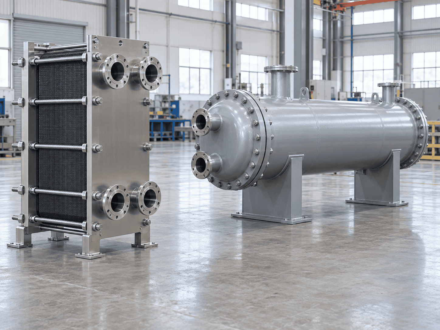
Industrial plate and shell-and-tube heat exchanger selection
Selection is service-driven. Fluid properties, fouling, cleaning access, pressure, temperature and maintenance strategy all affect the final choice.
Gasketed Plate-and-Frame
Why consider it

Compact liquid duties, close temperature approaches and access to the heat-transfer surfaces.

Verify before selection

Plate and gasket compatibility, channel dimensions, design limits and opening space. Extra plates still require available frame capacity and re-rating.

Brazed Plate
Why consider it

Compact assemblies for suitably clean and compatible fluids.

Verify before selection

Brazing-alloy compatibility, filtration, pressure and temperature limits, and a cleaning method that does not require opening the plate pack.

Semi-Welded Plate
Why consider it

Selected duties where welded passages reduce gasket exposure on one circuit.

Verify before selection

Remaining gasket exposure, fluid routing and the cleaning method for each side.

Fully Welded Plate
Why consider it

Selected services requiring welded plate construction and compact heat-transfer area.

Verify before selection

Construction-specific limits, inspection access, cleaning provisions and repair strategy.

Shell-and-Tube
Why consider it

Duties favoring tubular construction, selected metallurgy or specific mechanical requirements.

Verify before selection

Fluid allocation, tube geometry, fouling, thermal expansion and whether the selected construction allows bundle removal or mechanical cleaning.

Solids do not automatically rule out every plate exchanger.

Suitable wide-gap or application-specific plate arrangements may be available depending on the particle size, concentration and cleaning strategy.

Shell-and-tube does not automatically mean both sides are easy to mechanically clean.

Accessibility depends on the actual construction, removable components and which fluid is assigned to the tube or shell side.

TEMPERATURE PROGRAM

Temperature Approach Can Change the Size of the Same-Duty Skid

Two packages rated for the same heat duty can need different heat-transfer areas because their temperature driving forces differ. The closer the required outlet approaches the entering utility temperature, the more important the complete temperature program becomes.

Counterflow terminal differences ΔT₁ = Hot In − Cold Out ΔT₂ = Hot Out − Cold In
LMTD (ΔT₂ − ΔT₁) / ln(ΔT₂ / ΔT₁)

When both terminal differences are equal, the LMTD equals that common temperature difference.

CASE A

500 kW with a 10 K Minimum Terminal Difference

Hot side
70°C
50°C
21.50 m³/h water
Cold side
60°C
30°C
14.33 m³/h water
Smallest terminal difference 10 K
LMTD 14.43 K
Relative area 1.00
CASE B

500 kW with a 2 K Minimum Terminal Difference

Hot side
70°C
50°C
21.50 m³/h water
Cold side
68°C
30°C
11.32 m³/h water
Smallest terminal difference 2 K
LMTD 7.82 K
Relative area ≈ 1.85
WHY THIS MATTERS Same duty does not mean the same exchanger size.

If the overall heat-transfer coefficient and configuration factor remain unchanged, the lower LMTD in Case B requires substantially more heat-transfer area. The 1.85 ratio isolates the effect of temperature driving force; it is not a guaranteed equipment-size or price multiplier.

ILLUSTRATIVE HEAT RECOVERY 250 kW × 4,000 h = 1,000 MWh

Recovered heat is useful only when the receiving process can use it.

This figure represents gross transferred heat when both streams are available. Purchased-energy savings still depend on what the recovered heat replaces, the actual operating schedule, backup-system efficiency and additional pumping energy.

HYDRAULIC DESIGN

Budget Pressure Drop Across the Whole Circuit

The exchanger is only one source of hydraulic resistance. Valves, strainers, meters and connecting pipework also use the available pressure budget. Add losses along the same flow path, and calculate the hot and cold circuits separately.
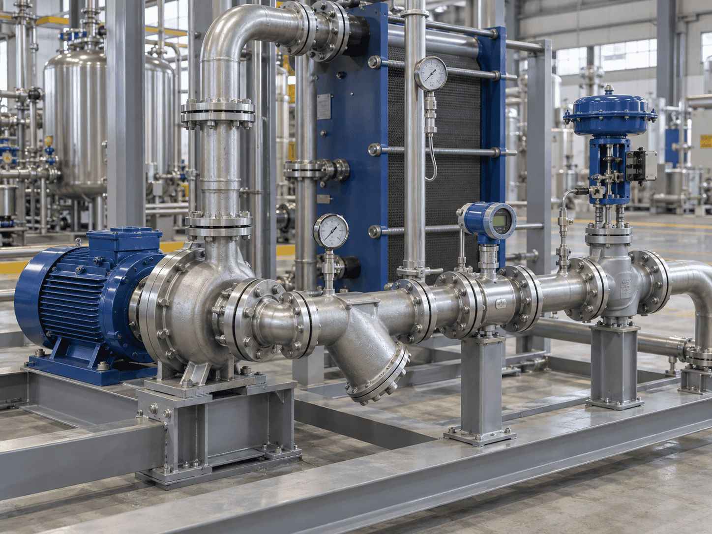
Heat exchange skid piping, pump, strainer and control valve details
Look beyond exchanger ΔP. Pumps, strainers, valves, flow meters and fittings all affect the available hydraulic margin.
ILLUSTRATIVE FLOW PATH 20 m³/h Water Circuit

These values explain the budgeting method. They are not recommended limits or standard skid ratings.

Heat exchanger 35 kPa
Control valve 20 kPa
Clean strainer 8 kPa
Flow meter 5 kPa
Piping & fittings 12 kPa
Clean-path total 80 kPa ≈ 8.15 m water head
With selected loaded-strainer case 97 kPa ≈ 9.89 m water head
WHAT CHANGED? Only the strainer loss increased in this example.
Clean strainer 8 kPa
→
Loaded-strainer case 25 kPa
=
Additional circuit resistance +17 kPa
ALLOWABLE ΔP

Specify where the pressure-drop limit applies.

Tell us whether your allowable pressure drop covers the exchanger alone, the skid from inlet to outlet, or the complete plant loop.

PUMP HEAD

Skid loss is not automatically the required pump head.

Pump selection also considers external piping, elevation, available inlet conditions, suction requirements and the intended operating range.

CONTROL VALVE

Do not select a control valve only by line size.

The valve must have enough usable differential pressure and authority to regulate the actual circuit across the required operating range.

OPERATING RANGE

Check Minimum, Normal and Maximum Operation—not Only Full Load

The rated design point is only part of a temperature-control specification. Define the combinations of flow, inlet temperature, outlet target and utility conditions that the package will encounter in production.

REFERENCE FLOW 100%
20 m³/h
25 → 45°C
Calculated duty ≈ 465 kW

Review full-load heat transfer, pressure losses and available utility capacity.

REFERENCE FLOW 50%
10 m³/h
25 → 45°C
Calculated duty ≈ 233 kW

Check valve operating position, changed hydraulic conditions and temperature response.

REFERENCE FLOW 20%
4 m³/h
25 → 45°C
Calculated duty ≈ 93 kW

Review equipment minimum-flow requirements, control resolution and circulation strategy.

IMPORTANT These three cases are energy-balance examples—not a guaranteed 5:1 turndown ratio.

A requirement for lower minimum load needs its own operating case, utility conditions, exchanger review and control assessment.

CONTROL REQUIREMENTS

Define the conditions behind the temperature tolerance.

Steady-State Tolerance How close must the controlled temperature remain to setpoint after the system stabilizes?
Transient Deviation How much temperature deviation is acceptable during a load or flow change?
Recovery Time How quickly must the process return to the specified band after a disturbance?
Operating Envelope Over what process flow, inlet temperature and utility conditions must those requirements apply?
STARTUP Cold startup may be more demanding than steady operation.

Initial equipment temperature, stored thermal mass and available utility conditions can change the required response.

SEASONAL CHANGE Cooling-water temperature may not stay constant all year.

Check summer and winter utility conditions where seasonal variation materially affects heat-transfer driving force.

PRODUCTION CHANGE Flow reduction and inlet-temperature change are different disturbances.

The same controller can behave differently when the process load changes through flow, temperature or both.

CONTROL STRATEGY

Match the Control Strategy to the Thermal and Hydraulic System

Start with the variable that must be controlled: process outlet temperature, loop supply temperature, flow or another agreed condition. Then select the valves, circulation arrangement, instruments and control interface to support that objective.
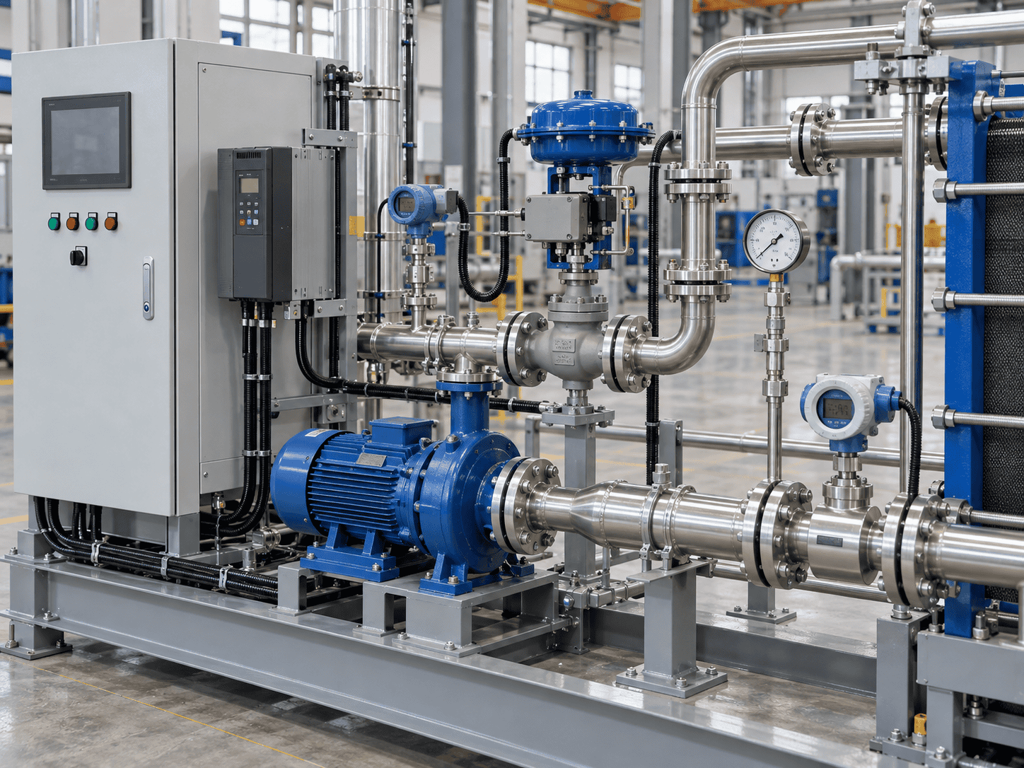
Heat exchange skid control valve, instrumentation, pump and control cabinet
Control equipment must match the circuit. A PLC, VFD or actuated valve does not by itself guarantee stable temperature control.
START WITH THE CONTROLLED VARIABLE What must remain stable when the process changes?
Process outlet temperature Temperature
Closed-loop supply condition Loop Control
Required circulation rate Flow
Plant control system command DCS / PLC
The valve, pump and control logic should be selected after the process objective and available differential pressure are understood.
Two-Way Utility Valve
Intended function

Modulate the heating or cooling utility flow to control the selected process temperature.

Design check

Required valve capacity, available differential pressure and usable operating range.

Three-Way Mixing or Diverting Valve
Intended function

Mix streams or redistribute flow where the hydraulic arrangement requires a bypass or recirculation path.

Design check

Valve function, location, branch balancing and the minimum flow required by the exchanger or pump.

Variable-Speed Circulation Pump
Intended function

Adjust circulation to a defined flow, differential-pressure or thermal-control objective.

Design check

Pump operating range, equipment minimum flow and coordination with the temperature-control loop.

Steam Valve & Condensate System
Intended function

Regulate steam input while maintaining reliable condensate removal from the exchanger.

Design check

Steam-space pressure, condensate backpressure, drainage route and low-load operation.

STEAM HEATING

Check the condensate return—not only the steam valve.

High Load Higher steam-space pressure

Condensate may discharge normally when enough differential pressure is available.

→
Reduced Load Steam valve throttles

Pressure inside the exchanger can fall as the control valve closes.

→
Stall Risk Return pressure may dominate

Condensate drainage can become unreliable if the available pressure is too low.

Selecting a larger steam trap does not create missing differential pressure. The steam and condensate arrangements must be evaluated together.
INSTRUMENTS & PROTECTIVE FUNCTIONS

Measure what the control logic actually depends on.

Temperature Terminal temperatures and controlled outlet temperature as required.
Pressure Selected suction, discharge, process and utility pressure measurements.
Flow Process or circulation flow where it is required for control or verification.
Differential Pressure Across selected equipment where fouling or hydraulic condition needs monitoring.
Pump Status Run, trip, duty/standby status and VFD feedback where specified.
Valve Feedback Position indication or fail-state confirmation where the control philosophy requires it.
Define alarm and interlock responses through a cause-and-effect schedule.

Low flow, excessive temperature, pump failure, sensor failure and loss of utilities can require different responses. Heating isolation, continued cooling and pump run-on should be treated as separate engineering decisions rather than one universal shutdown rule.

MATERIALS & FOULING

Specify the Entire Wetted Path—and Plan for Fouling

Material selection applies to everything the fluid touches, not only the heat-transfer surface. Review plates or tubes, piping, valves, pump parts, gaskets, seals and instrument connections against both the operating fluids and cleaning chemicals.

WETTED PATH One incompatible component can define the service limit of the whole circuit.
Heat Transfer Surface Plates / Tubes
→
Process Piping Pipe / Fittings
→
Flow Control Valves
→
Circulation Pump Wetted Parts
→
Measurement Instrument Connections
Fluid Chemistry

What is actually in the process fluid?

Provide fluid identity, concentration, known contaminants, pH and relevant chloride or corrosive species where applicable.

Design decision Select compatible alloys, gasket materials, seals and instrument wetted parts.
Temperature Envelope

Normal operation is not the only temperature condition.

Include startup, maximum operating temperature, cleaning temperature and relevant upset conditions.

Design decision Verify metals, elastomers, gasket compounds and seals across the full required temperature range.
Solids & Deposits

Particle size and fouling behavior influence the channel design.

Define suspended solids, fibers, crystals, scale tendency and precipitation risk where these can affect operation.

Design decision Choose passage geometry, filtration strategy, velocity and cleaning access accordingly.
Sealing Materials

Do not specify only “stainless steel” and ignore the elastomers.

Process exposure, cleaning chemicals, temperature and replacement requirements all affect gasket and seal selection.

Design decision Specify the actual compound or approved compatibility requirement for the service.
Hygienic Requirements

Sanitary construction requires more than a material grade.

Define product-contact surfaces, drainability, cleaning method, surface finish and documentation expectations.

Design decision Apply the required product-contact construction and inspection criteria to the relevant circuit.
MATERIAL OPTIONS

Choose materials from the service conditions—not from one default grade.

304 Stainless Steel Selected compatible water and process services where corrosion conditions allow.
316L Stainless Steel Commonly considered for more demanding process and hygienic duties, subject to actual chemistry.
Titanium Available for selected aggressive services where its corrosion resistance is appropriate.
Duplex Stainless Steel Considered for selected corrosion and mechanical design requirements.
Carbon Steel Suitable for compatible services or non-wetted structural components where specified.
Project-Specified Alloy Other alloys can be evaluated when the process chemistry or project specification requires them.
CLEANING STRATEGY

Plan the cleaning method before finalizing the skid layout.

Clean in Place

Provide the required circulation, drain, vent and chemical-compatibility provisions for the selected equipment.

Open for Inspection

Reserve access to open plate packs, covers, channels or removable components without dismantling unrelated skid equipment.

Remove for Service

Define lifting, isolation and withdrawal space for pumps, strainers, tube bundles or other serviceable components.

FOULING CHECK Do not diagnose fouling from one pressure reading alone.

Fouling can reduce heat-transfer performance and may increase pressure drop, but the diagnosis should compare flow, temperatures, duty and differential pressure under comparable conditions before deciding on cleaning or replacement.

REDUNDANCY STRATEGY

Define the Capacity That Must Remain After an Outage

A second pump or exchanger is useful only when it supports the required operating strategy. Start by defining the essential duty that must remain available while one item is out of service.

KEY QUESTION What capacity must remain if one unit is unavailable?

Equipment count alone does not define redundancy. Remaining duty depends on the rating of each unit, utility availability, flow distribution, isolation and the control sequence used during changeover.

Single Train 1 × 100%
Installed nominal capacity 100%
After one unit is unavailable 0%

Lowest installed capacity, but no equipment standby for the heat-transfer train.

Split Duty 2 × 50%
Installed nominal capacity 100%
After one unit is unavailable 50%

Two units do not automatically provide full-duty standby when each is rated for only half the design duty.

N+1 Split Duty 3 × 50%
Installed nominal capacity 150%
After one unit is unavailable 100%

Two duty units plus one spare can maintain full nominal duty when flow distribution and controls support the arrangement.

COMMON POINTS OF FAILURE

Review shared components before calling the system redundant.

Common Strainer A single blocked or isolated strainer can disable more than one downstream train.
Common Power Feed Dual pumps do not provide electrical redundancy when both depend on the same unavailable source.
Common Control Panel One controller, network or panel can remain a single point of failure unless the project requires otherwise.
Common Header Isolation, valve arrangement and hydraulic balance determine whether one unit can be serviced independently.
PUMPS Duty/standby pumps protect circulation—not the exchanger itself.

A standby pump can keep the loop moving after a pump failure, but it does not keep a single exchanger available while that exchanger is opened for cleaning.

HEAT EXCHANGERS Define whether maintenance must occur without reducing thermal duty.

Full exchanger standby requires enough remaining heat-transfer area and utility capacity to maintain the required process duty.

CHANGEOVER Specify how the spare train enters service.

Manual isolation, automatic changeover, warm standby and immediate restart are different operating requirements.

MAINTENANCE ENVELOPE

The Installation Footprint Must Include Maintenance Access

Shipping dimensions show how the package moves to site. They do not show every space needed to operate, open or maintain it. Review the proposed skid in its actual installation area with the maintenance envelope and removal routes visible.
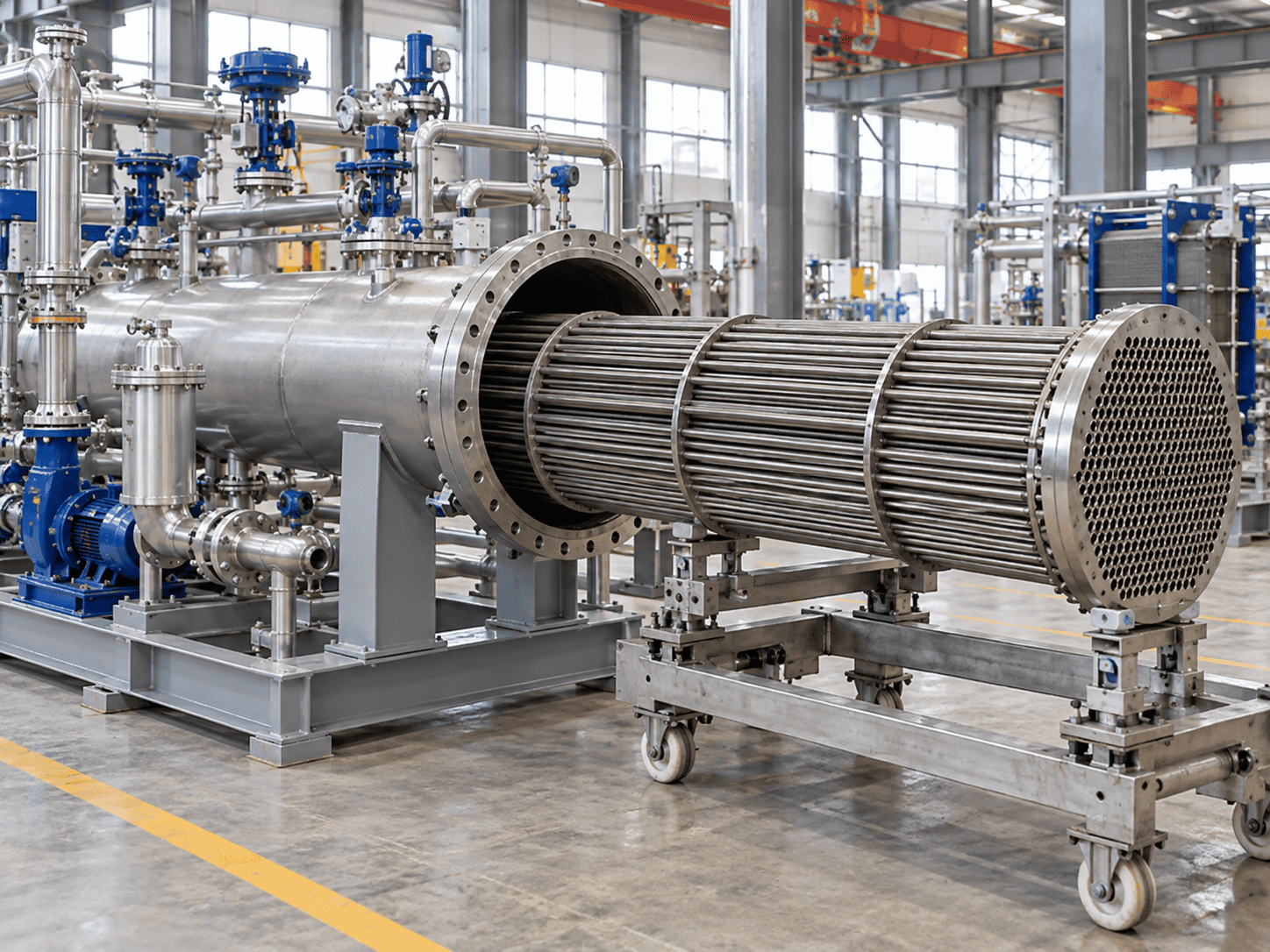
Heat exchange skid maintenance access and equipment service clearance
Equipment footprint ≠ maintainable footprint. Opening, removal, lifting and service clearances need to be considered before the skid is placed on site.
THREE DIFFERENT DIMENSIONS Do not treat transport size, installed footprint and maintenance envelope as the same number.
Transport Dimension What must pass through the route to site?

Check shipping modules, doorways, corridors, lifting points and transport restrictions.

Installed Footprint What space does the operating package occupy?

Include the skid frame, connection zones, insulation and required operating access.

Maintenance Envelope What extra space is needed to service the equipment?

Include opening travel, component withdrawal paths, lifting access and working clearance.

Plate-and-Frame Exchanger
Access to define

Plate-pack opening travel, plate handling space, tightening-bolt access and room to remove plates safely.

Removable-Bundle Shell-and-Tube
Access to define

Channel or head removal, full tube-bundle withdrawal path and the lifting or pulling arrangement needed for maintenance.

Pumps & Strainers
Access to define

Motor, coupling, seal, casing or basket removal space with suitable isolation and room for safe servicing.

Valves & Instruments
Access to define

Manual operation, calibration, transmitter removal, actuator service and access to isolation points.

Control Panel
Access to define

Door opening, cable access, ventilation and service space with protection from nearby hot, wet or leaking equipment.

SITE INTERFACES

Show the installer what connects, supports, drains and lifts.

Connection Positions Process, utility, drain, vent and electrical interfaces with size, standard and orientation.
Dry & Operating Mass Weights needed for foundation review, lifting and handling planning.
Foundation Interface Base dimensions, fixing points, anchor requirements and any grouting or leveling provisions.
Lifting & Handling Approved lifting points, module splits and removal routes for major serviceable components.
Thermal Movement Allowances for expansion where hot pipework or equipment can impose movement on the skid.
Insulation & Drainage Space for insulation, low-point drains, vents and access after insulation is installed.
NOZZLE LOADS Site piping should not use the exchanger or pump connection as a pipe support.

Review external pipe support, alignment and thermal movement so field piping does not impose unassessed loads on exchanger nozzles, pump flanges or skid-mounted equipment.

SERVICE ROUTE

Check how the largest removable component leaves the area.

Isolate Create a safe maintenance boundary.
→
Open Provide access to covers, frames or bolted joints.
→
Lift / Withdraw Reserve enough clear travel and lifting space.
→
Remove from Area Confirm the component can pass through the service route.
DESIGN BASIS & DELIVERABLES

Agree the Design Basis Before You Agree the Code List

A heat exchange skid can include pressure-retaining equipment, process piping, instruments, controls and electrical assemblies. The applicable requirements depend on what is inside the package, where it will be installed and what the purchaser specifies.

APPLICABILITY BY SCOPE

Match the requirement to the component it actually governs.

Pressure Equipment Exchanger / Vessel

Applicable pressure-vessel rules, including ASME BPVC Section VIII where specified and within the contracted scope.

ASME Section VIII
Process Piping On-Skid Piping

ASME B31.3 where applicable, including interconnecting piping within packaged process equipment assemblies.

ASME B31.3
Heat Exchanger Construction Shell-and-Tube

TEMA requirements can be applied where specified by the purchaser alongside the applicable pressure-vessel rules.

TEMA
European Supply Pressure Equipment

Evaluate the Pressure Equipment Directive and the applicable conformity route for the equipment or assembly being supplied.

EU Pressure Equipment Directive
Electrical & Area Classification Panel / Field Components

Apply destination and project requirements for panel construction, hazardous-area classification, installed components and site interfaces.

Defined by project and destination requirements
Steam service alone does not automatically determine the piping code.

The governing requirement should follow the facility, service and piping-system scope rather than the presence of steam by itself.

PROJECT DELIVERABLES

Define the document package before fabrication starts.

Each group below can be agreed at quotation stage so there is no ambiguity at final handover.

Process & Thermal Design basis, heat balance and exchanger rating
Design basis Heat balance Exchanger rating Specified operating cases
Mechanical General arrangement and equipment definition
General arrangement Equipment datasheets Material schedule Connection details
Piping & Controls P&ID, instrument list and control narrative
P&ID Valve and instrument lists Control narrative Cause-and-effect schedule
Electrical Panel, wiring and communication interfaces
Panel drawings Wiring drawings I/O list Communication interface
Quality & Handover Inspection records and final project documents
Inspection and test plan Specified material/test records As-built documents Operating instructions
INSPECTION & ACCEPTANCE

Separate Fabrication Inspection, Functional FAT and Thermal Acceptance

The word “tested” should identify what was actually verified. Mechanical integrity, instrument logic and thermal performance are different acceptance activities and should have separate criteria.
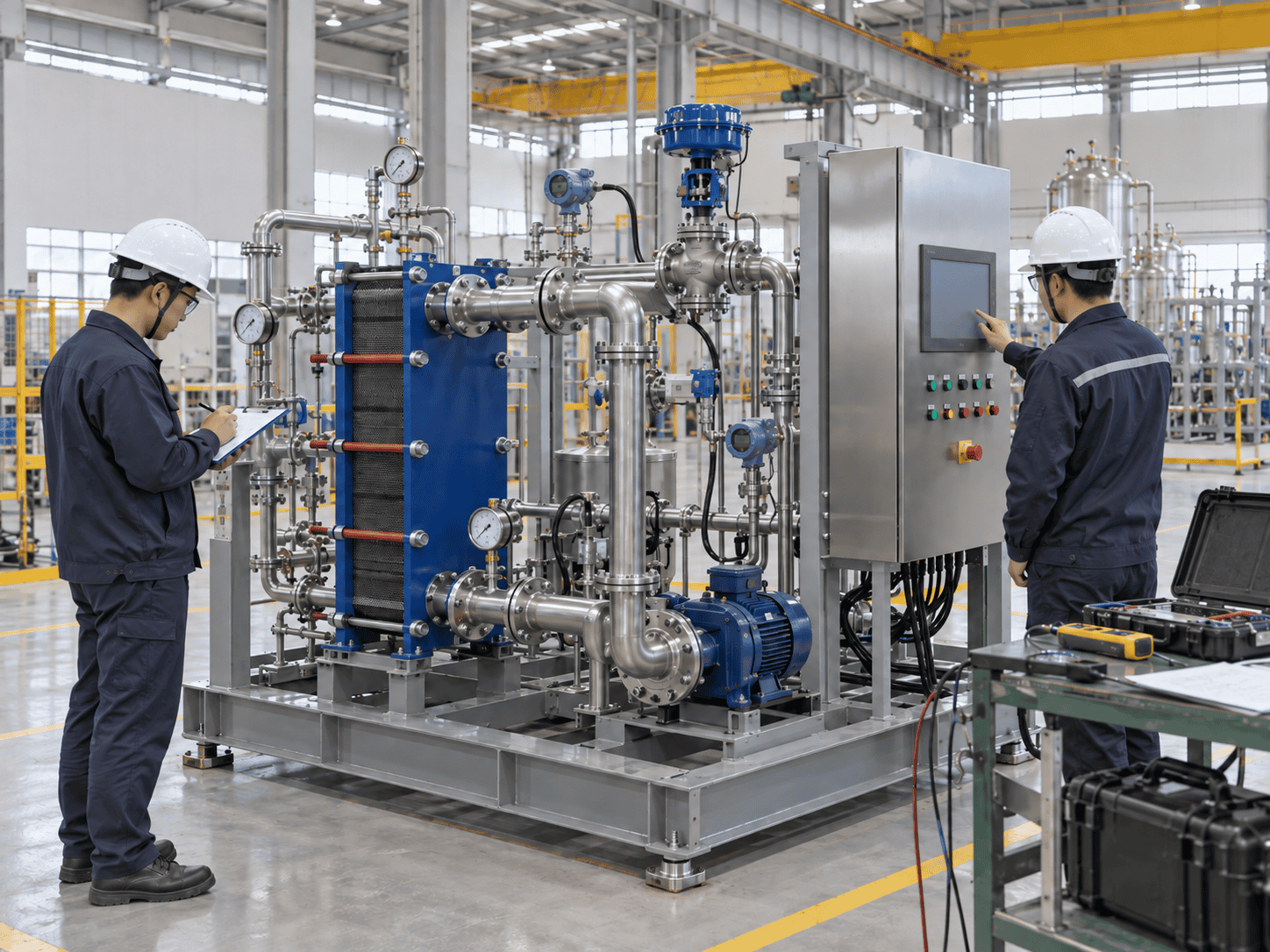
Heat exchange skid factory inspection and acceptance testing
Factory verification should produce evidence—not only a statement. Define what was inspected, how it was tested and which checks remain dependent on site conditions.
VERIFICATION LADDER

Each layer answers a different question.

Fabrication & Assembly Was the skid built as specified?

Materials, dimensions, connections, weld examination, installed equipment and cleanliness.

Pressure / Leak Test Is the defined pressure boundary acceptable?

Test medium, pressure, duration, boundary and protected components are agreed before testing.

Functional FAT Does the control logic behave as intended?

I/O checks, simulated signals, valve stroke, pump/VFD operation, alarms and agreed interlocks.

Thermal Acceptance Can the system demonstrate the contracted heat-transfer duty?

Requires agreed flow, temperatures, test utilities, stabilized conditions and measurement methods.

Site Integration Does the installed package work with the real plant?

Final utilities, field connections, communications and commissioning responsibilities are confirmed on site.

DON'T CONFUSE THE EVIDENCE

Three common acceptance mistakes

Pressure Test ≠ Heat Duty

A hydrostatic or pneumatic test verifies the defined pressure boundary. It does not demonstrate exchanger thermal capacity.

Simulated Signal ≠ Process Performance

A simulated sensor input can prove logic and alarms without transferring actual process heat.

FAT Complete ≠ Site Complete

Some checks depend on final utilities, connected loads, field piping and the real plant control system.

THERMAL ACCEPTANCE PATH

Choose the verification route that fits the project.

Factory Thermal Test
Use when factory utilities can reproduce the required test conditions.

Define flow, temperatures, stabilization, measurement accuracy and acceptance tolerance before the test.

Site Performance Test
Use when actual plant utilities or loads are required to demonstrate the duty.

Confirm which party supplies instruments, operating conditions, data collection and final acceptance records.

Rating + Defined Verification
Use when full-load thermal testing is not practical.

Combine the exchanger rating with agreed pressure, mechanical and functional verification without claiming a thermal test that did not occur.

HANDOVER Separate completed factory evidence from site-dependent checks.

The final data package should identify completed inspections, unresolved site checks, as-built documentation, operating instructions and any acceptance activities that remain after shipment.

APPLICATIONS

Heat Exchange Skids for Different Process Duties

The industry identifies the context; the actual fluids and operating conditions define the equipment. ChannelVessel configures heat exchange skid packages around the process duty, utility conditions, materials, controls and maintenance requirements of each application.

Chemical Processing →

Reaction loops, process heating, cooling and heat recovery

Selection focuses on fluid compatibility, fouling behavior, changing thermal loads and the consequences of a temperature excursion.

Reactor loops Corrosive media Heat recovery
Petrochemical Processing →

Process cooling, utility interfaces and recovery duties

Define the mechanical design basis, normal and upset conditions, maintenance access and required availability before selecting the package arrangement.

Utility integration Process cooling High availability
Oil & Gas →

Temperature control for oil, glycol and utility circuits

The enquiry should define viscosity, contamination, installation environment, area classification and the duty that must remain during maintenance or an outage.

Glycol loops Oil cooling Hazardous areas
Food & Beverage →

Product or utility-side heating and cooling

Product-contact service requires explicit hygienic, surface-finish, drainability and cleaning requirements; stainless steel alone does not define a sanitary system.

Hygienic service CIP Temperature control
Pharmaceutical Processing →

Controlled process temperature and clean utility interfaces

Define which circuit contacts the process together with cleaning, traceability and any validation-support documentation required by the project.

Clean utilities Traceability Documentation
New Energy →

Cooling and temperature-control loops for energy equipment

Identify the actual coolant, cleanliness requirements, equipment interfaces and availability targets rather than applying one generic configuration to every application.

Battery processes Electrolyzer cooling Closed loops
Industry names are not design inputs.

The final skid still needs fluid properties, flow, temperatures, pressure-drop limits, utilities, control objectives and project requirements before the exchanger and package can be selected.

FAQ & RFQ DATA

Heat Exchange Skid Questions—and the Data Needed for a Quote

You do not need a completed engineering package to start an enquiry. Send the process information you already have, identify unknown values and let the remaining design inputs be clarified during technical review.

COMMON QUESTIONS

What buyers usually need to confirm before ordering

What is included in a heat exchange skid?
A package can combine the exchanger, structural frame, piping, valves, instruments and controls. Pumps, insulation, steam accessories and auxiliary equipment depend on the agreed configuration. The quotation should distinguish included items, options and work by others.
Is a heat exchange skid the same as a chiller?
No. A heat exchange skid transfers energy between available streams. It does not automatically produce chilled water. A chiller, boiler or other utility source remains separate unless it is expressly included in the package scope.
Can the same nominal kW rating cover different temperatures?
Only after checking the rating at the revised conditions. The same duty can require a different heat-transfer area, flow rate or exchanger construction when the temperature driving force or fluid properties change.
How close can the outlet temperature get to the utility temperature?
The achievable approach depends on the flow arrangement, fluids, area, allowable pressure drop and operating conditions. There is no single minimum approach that applies to every heat exchange skid.
Does every package need a skid-mounted pump?
No. An existing plant pump may serve the circuit when its available flow and head meet the complete system requirements. A dedicated skid pump is used where the hydraulic arrangement or control strategy requires one.
Do two exchangers provide full standby capacity?
Only when the remaining equipment can meet the essential duty at the specified conditions. Two exchangers each rated for 50% duty do not provide full-duty standby. Utilities, isolation and flow distribution also matter.
Does FAT prove the actual heat-transfer capacity?
Not automatically. A functional FAT may use simulated signals and may not have the utilities needed for a full-load thermal test. Thermal acceptance requires defined operating conditions, measurements and acceptance criteria.
What affects the price and delivery schedule?
Major drivers include exchanger construction, duty and temperature approach, design pressure and temperature, wetted materials, pumps, redundancy, controls, inspection, documentation and transport restrictions.
DETAILED ENGINEERING DATA

Add these inputs when they are available

These details reduce assumptions during exchanger sizing, pump selection and control design.

Each Fluid Circuit Density / viscosity / specific heat Min / normal / max flow Inlet / outlet temperatures Operating & design pressure Allowable pressure drop Fouling / solids / cleaning
Package Requirements Temperature tolerance Standby duty Pump responsibility Power supply PLC / DCS interface Communication protocol
Installation & Compliance Connection standard Footprint restrictions Indoor / outdoor environment Area classification Applicable code Inspection / document scope
READY FOR REVIEW?

Turn Your Process Conditions Into a Defined Skid Package

Send your operating data and drawings to ChannelVessel. We can develop a proposal covering the thermal basis, exchanger arrangement, pump and control scope, site interfaces and agreed inspection or acceptance requirements.

Request a Skid Quote Send Your P&ID / Drawings Start with your process conditions. Define the package before comparing the price.
Scroll to Top
DRAWING & FILE REVIEW

Send Your Drawings

Upload your drawings, datasheets or existing specifications. Our engineering team will review the files and respond with technical feedback.

Engineering Review

Drawings, specifications and process requirements

Confidential File Handling

Project files are used only for technical review and quotation

Faster Technical Feedback

Clearer inputs help us respond more accurately and efficiently

DRAWING & FILE REVIEW

Send Your Drawings

Upload your drawings, datasheets or specifications. Our engineering team will review your files and provide technical feedback.

Contact Form Demo (#3)
Project Protected NDA available
12h Response
ASME / PED
AFTER SUBMISSION
01 Review
→
02 Confirm
→
03 Quote
TECHNICAL QUOTATION

Get a
Technical Quote

Tell us what you need. Our engineering team will review your requirements and respond within 12 hours.

Engineered for Your Application

From concept to certified manufacturing

Global Compliance

ASME, PED and other international standards

Expert Support

Direct access to our engineering team

TECHNICAL QUOTATION

Get a Technical Quote

Tell us what you need. Our engineering team will review your requirements and respond within 12 hours.

Contact Form Demo
Project Protected NDA available
12h Response
ASME / PED
AFTER SUBMISSION
01 Review
→
02 Confirm
→
03 Quote