
Custom Reactor Vessels Engineered Around Your Process
We engineer and fabricate custom reactor vessels around your reaction chemistry, working volume, heat-transfer duty, mixing requirements, pressure or vacuum conditions, and material compatibility.
From jacket configuration and agitator design to vessel materials, nozzles, internals and instrumentation, each reactor is developed as an integrated process and mechanical system rather than a standard vessel with added options.
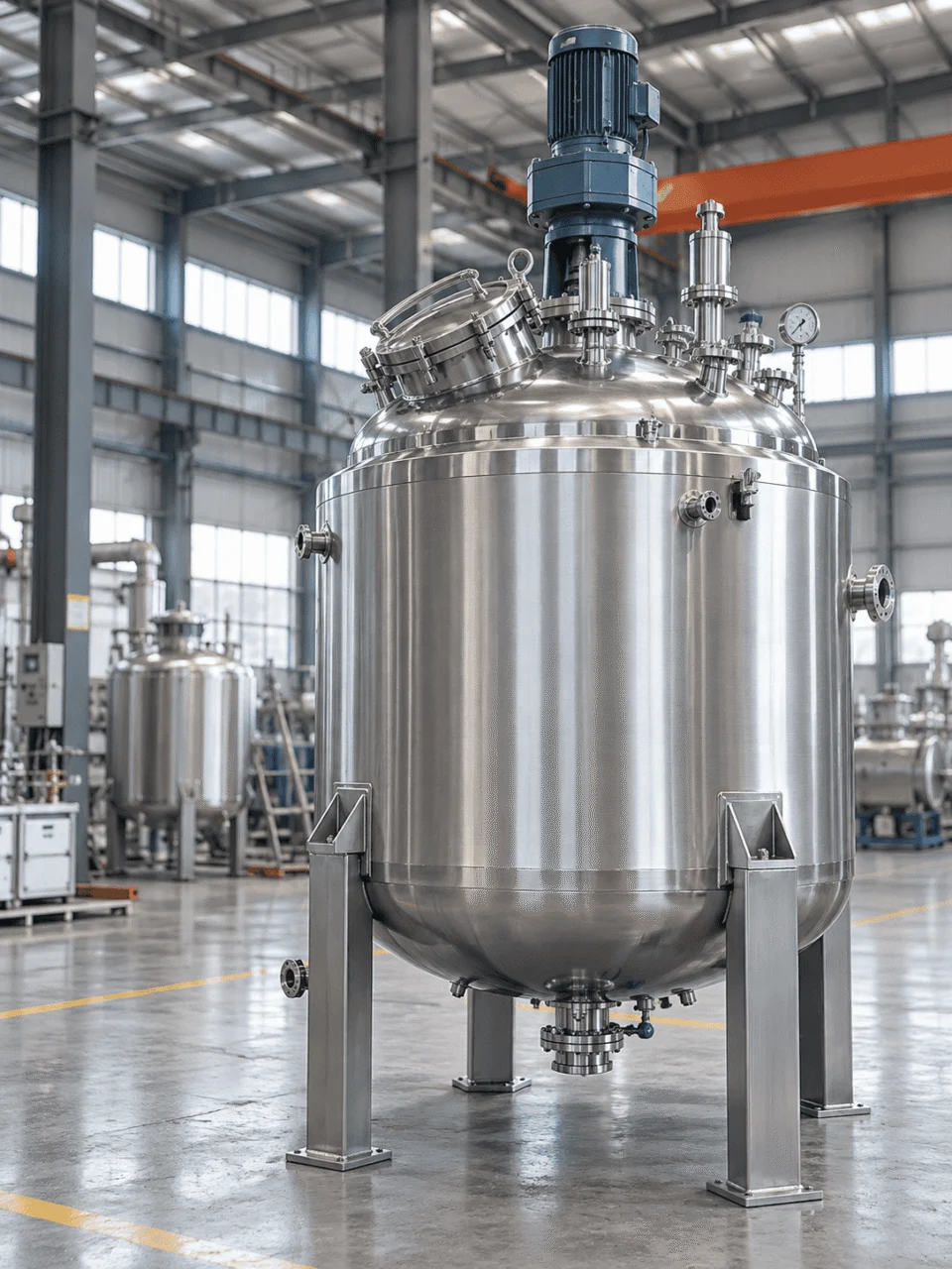
One Process Change Can Reshape the Entire Reactor Design
A custom reactor should not be engineered by selecting vessel size, jacket type, agitator and material as separate options. These decisions interact with one another, and a change in one process condition can affect several mechanical and thermal design choices at the same time.
Viscosity can change mixer torque and heat-transfer performance. A shorter heating time can change thermal duty and jacket requirements. More aggressive chemistry at elevated temperature can change material selection, fabrication controls and project cost.
These relationships are part of the broader pressure vessel design process, where process inputs are translated into a safe and manufacturable vessel configuration.
As product viscosity rises, mixing resistance increases and flow inside the vessel can change substantially.
The mixer may require a different gearbox, shaft diameter or impeller arrangement.
Torque, bending and radial loads must be considered at the agitator nozzle and vessel head.
Impeller geometry, diameter, speed and baffles may need to change to maintain circulation.
Reduced internal convection can increase the heat-transfer area or utility demand required for the batch.
Reducing the time allowed to move a batch from its initial temperature to the target temperature increases thermal duty.
The reactor must transfer more energy into the batch within the same operating cycle.
The required jacket area may increase, or an internal coil or external loop may become necessary.
Conventional, dimple or half-pipe construction may be evaluated against duty and utility conditions.
Steam pressure, hot-oil temperature, cooling-water temperature and flow affect both process and mechanical design.
Corrosion behavior depends on more than the chemical name alone. Concentration, temperature and contaminants can change material suitability.
316L may no longer be suitable and a duplex, nickel alloy or other material may need to be evaluated.
Welding procedures, filler materials, heat input and post-fabrication treatment may require tighter control.
Corrosion allowance, lining strategy, nozzle materials and sealing details may need to be reconsidered.
Special-alloy procurement, welding qualification and inspection requirements can materially affect the project schedule.
A Reliable Reactor Design Starts With the Right Process Data
Before vessel geometry, jacket configuration or agitator type can be finalized, the design basis must define what the reactor is expected to contain, withstand, mix, heat, cool and discharge.
You do not need a finished mechanical drawing to begin. An existing drawing, process datasheet, P&ID or a clear set of operating conditions is enough for an initial engineering review.
The goal is to establish a complete vessel design basis before detailed mechanical design begins.
Define what is inside the reactor and how the batch behaves.
A “5,000 L reactor” is not a complete specification. We first need to know whether 5,000 L means working volume or total vessel volume.
Working volume, headspace and phase behavior influence vessel capacity, geometry, agitator arrangement and usable operating level.
Foaming, gas evolution or solids loading can require additional freeboard, different nozzle locations, altered agitation or a larger gross vessel volume than the nominal batch size suggests.
Define how far and how fast the batch must be heated or cooled.
“Heat to 120°C” does not define the jacket. A useful design input is closer to “25°C to 120°C in 90 minutes.”
Temperature change and required cycle time determine thermal duty before jacket type or heat-transfer area can be selected.
Steam pressure, thermal-oil temperature, cooling-water temperature and available utility flow can change the practical heat-transfer configuration even when the batch size is unchanged.
Define the vessel side and jacket side as separate pressure boundaries.
Reactor pressure, vacuum service and jacket pressure should never be reduced to one generic pressure value.
Internal pressure, external pressure and jacket pressure affect different parts of the mechanical design and must be defined independently.
Vacuum can govern shell stability even when positive operating pressure is low, while jacket pressure can drive a separate set of mechanical checks for the heat-transfer boundary.
Define the actual corrosion environment, not only the chemical name.
Material suitability can change with concentration, temperature, contaminants and cleaning conditions.
Detailed material selection should be based on the combined process environment.
Chemistry and temperature can change alloy choice, corrosion allowance, weld procedures, sealing details and surface-treatment requirements.
A material that performs well at one concentration or temperature may not be suitable at another, so chemistry data should be reviewed as an operating envelope rather than a single product name.
Define where the reactor will be installed, connected and maintained.
A reactor can be manufacturable yet still be difficult to transport, install or service if site constraints are ignored.
Site conditions affect support design, orientation, nozzle accessibility, overall dimensions, transport planning and maintenance clearance.
Equipment should be checked against doorways, lifting routes, platform elevations, pipe racks and service access before fabrication is released.
The more complete the design basis, the fewer assumptions need to be carried into reactor configuration, mechanical design and quotation.
How Process Requirements Become a Reactor Configuration
A custom reactor configuration is the result of multiple engineering decisions made together. Working volume influences geometry and headspace, heat duty affects the heat-transfer system, viscosity and solids affect agitation, chemistry influences materials and sealing, and pressure conditions shape the mechanical design envelope.
Working volume, headspace, foaming and gas disengagement influence overall vessel geometry.
Heating, cooling and reaction duty determine the heat-transfer architecture rather than the other way around.
Viscosity, solids, gas dispersion, suspension and shear sensitivity shape the agitation system.
Concentration, temperature, contaminants and cleaning conditions influence materials and sealing details.
Operating pressure, vacuum and jacket conditions define separate mechanical design requirements.
Footprint, height, piping interfaces, transport and maintenance access affect the final arrangement.
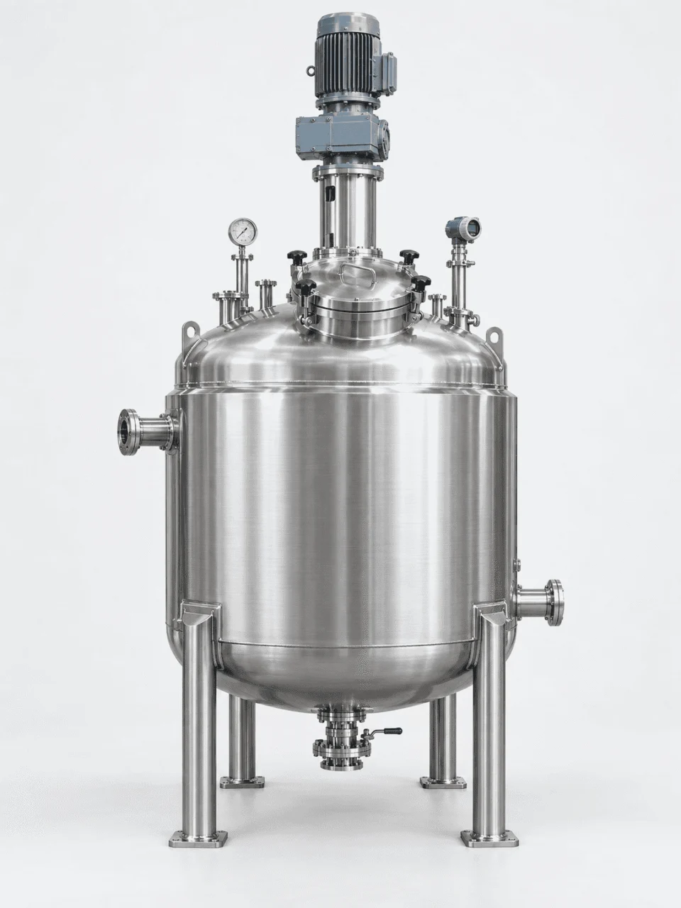
Aspect ratio, headspace, mixing geometry, heat-transfer area and installation limits can lead to different vessel dimensions for the same nominal batch size.
The objective is not to add as many features as possible. It is to translate the process design basis into the simplest reactor configuration that can meet the required mixing, thermal, mechanical, material and operating conditions.
Size the Heat Duty Before Choosing the Jacket
The heat-transfer system should be selected from the required batch duty, temperature change, cycle time and available utilities—not from jacket type alone. The same reactor volume can require very different heat-transfer architecture when the required heating or cooling time changes.
This simplified example calculates sensible heat only. Reaction heat, vessel heat capacity, heat loss, phase change and design margin must be considered separately when applicable.
Q = m × Cp × ΔT
Shorter cycle time means the same energy must be transferred at a higher average rate.
Based on 1,053,000 kJ transferred over 90 minutes.
Heat Duty Is Only the First Step
Once the required duty is known, the available temperature driving force and overall heat-transfer coefficient determine how much effective transfer area is required.
Viscosity, agitation, fouling tendency and phase behavior affect the internal heat-transfer coefficient. A larger jacket cannot always compensate for poor product-side circulation.
When the Heat-Transfer Configuration Changes
The selected configuration should follow duty, utility pressure, required transfer area, cleanability and process constraints.
Often suitable for moderate thermal duty and relatively straightforward utility conditions.
Considered when compact construction and improved utility-side flow distribution are useful.
Often evaluated for higher utility pressure, controlled flow path or more demanding duty.
Can add transfer area when the external jacket alone is insufficient, but affects cleaning, agitation and maintenance.
May be evaluated when jacket area or internal circulation cannot provide the required duty efficiently.
The final duty and utility conditions determine the most suitable jacketed reactor configuration for the process.
Three Inputs That Sound Complete but Are Not
The starting temperature and required heating time are still needed to establish the duty.
Steam pressure, supply condition, condensate arrangement and available flow influence the usable driving force.
The limiting resistance may be inside the vessel, especially when viscosity is high or mixing is weak.
RPM Alone Does Not Define Mixing Performance
Two reactors can run at the same speed and produce completely different flow, suspension and heat-transfer performance. Viscosity, density, impeller diameter, vessel geometry, solids loading and the required mixing outcome all matter.
The agitator should be engineered from the process duty first, then translated into impeller geometry, shaft size, gearbox torque, baffles, sealing and vessel-head loads.
Low viscosity, larger circulation pattern and relatively low flow resistance can produce strong bulk movement at the same shaft speed.
Higher viscosity can reduce circulation, increase torque and demand a different impeller, shaft or gearbox even when the speed does not change.

Reynolds number helps describe the flow regime, but it is not a stand-alone mixer sizing rule. Impeller geometry, power, torque, vessel proportions and process objectives still need to be evaluated together.
Start With the Required Process Behavior
The right question is not “What RPM do you want?” but “What must the batch actually do inside the vessel?”
Torque, radial load, axial load and bending moment do not stop at the gearbox. They are transferred into the agitator mounting, vessel head, reinforcement and support structure.
For that reason, the agitator should be defined early enough for mechanical design to account for the actual mixer loads rather than treating the mixer as a late-stage accessory.
Select the Material From the Process Environment — Not From Habit
304L, 316L, duplex, nickel alloys and titanium are only candidate materials. The right choice depends on the complete corrosion environment, including chemistry, concentration, temperature, chlorides or halides, cleaning conditions and product-purity requirements.
Base chemicals, solvents, reaction intermediates and expected by-products should all be reviewed before a material is selected.
The same chemical can show different corrosion behavior at different concentrations, so a single material rule should not be applied blindly.
Higher temperature can accelerate corrosion or change the dominant corrosion mechanism, which is why operating and design temperature both matter.
Where chlorides or other halides are present, localized corrosion resistance may become more important than general corrosion resistance alone.
A vessel may be compatible with the process fluid but still be vulnerable to a stronger cleaning chemical used during maintenance or CIP.
When contamination limits are tight, product-contact materials, surface condition and wetted-component consistency need to be considered together.
Screen the Process First, Then Narrow the Material
Moving to a higher-alloy material is not automatically better. The objective is to find the material that is compatible with the process, fabrication method, mechanical requirements and project economics.
Detailed material selection should be based on the full operating envelope rather than alloy grade alone.
Material Selection Extends Beyond the Vessel Shell
A corrosion-resistant shell does not protect the process if a nozzle, thermowell, agitator, dip pipe or seal component uses an incompatible wetted material.
Product-contact materials should be reviewed as one system so that the weakest wetted component does not become the corrosion or contamination failure point.
When Material Selection Should Be Reviewed Again
A material selected at one temperature may need to be reassessed when the operating range increases.
A change in concentration can alter corrosion behavior even when the chemical species stays the same.
New cleaning chemicals or stronger concentrations should be checked against every wetted component.
Changes in contaminants can shift the corrosion risk and may require another compatibility review.
Define the Mechanical Design Envelope Before Finalizing the Vessel
Pressure is only one part of the reactor load case. The vessel chamber, jacket chamber, vacuum condition, design temperature, mixer loads, piping loads, supports and site loads must be considered together before shell, head, nozzle and support calculations are finalized.
Pressure is only one part of the load case.A reactor may be specified, for example, for pressure or vacuum on the vessel side while the jacket operates at a different utility pressure and temperature.
Mechanical Calculations Follow the Applicable Code and Project Load Cases
Final shell, head, nozzle reinforcement and support calculations depend on material properties, design conditions, corrosion allowance, fabrication details and the applicable design code.
Our vessel design basics and codes and standards resources explain how these inputs fit into the broader pressure-vessel engineering process.
For projects specified to ASME Section VIII, Division 1, design, fabrication, inspection, testing and certification requirements are applied together with the project design conditions.
View ASME BPVC informationNozzle Layout Is a Process Decision — Not Just a Drawing Detail
Every process connection competes for space on the reactor. Feed nozzles, thermowells, relief connections, manways, dip pipes, spargers and cleaning connections must be positioned around the agitator envelope, internal components, piping direction, drainage and maintenance access.
A good layout should work during operation, inspection and service—not only fit on the general arrangement drawing.
The top head must accommodate the agitator, manway, process connections, instruments, venting and maintenance clearances without creating interference.
Marker positions are illustrative layout zones only. Final nozzle orientation depends on the P&ID, agitator envelope, connected piping, platform access and maintenance clearance.Feed location, dip-pipe depth, sparger position and outlet placement should be reviewed against the agitator and internal circulation pattern to avoid short-circuiting, poor dispersion or inaccessible internals.
Thermowells, level devices and sampling points need enough insertion and withdrawal clearance while staying outside the rotating agitator envelope and avoiding baffles or internal supports.
Connection size, location and routing should match the project venting and relief requirements while preserving access for inspection, maintenance and connected piping.
Manways, CIP connections, drains and agitator service space should be checked against piping, platforms and lifting clearance before the GA drawing is approved.
Connections Must Work With the Reactor — Not Against It
Instrument insertion must remain outside the rotating envelope and still reach a representative process region.
A manway loses practical value if connected piping, platforms or insulation prevent it from opening or being accessed safely.
Insertion depth and orientation must be checked against the shaft, impeller path, baffles and expected internal flow.
The discharge point should support the required emptying and drainage behavior rather than simply occupy the easiest available location.
Final nozzle size, opening reinforcement and local mechanical checks are completed as part of the pressure-vessel design after the process layout has been reviewed.
Cleanability Is Designed Into the Reactor — Not Added by Polishing
A smooth product-contact surface matters, but surface finish alone does not make a reactor easy to clean. Internal geometry, weld condition, drainability, retained-product zones, cleaning coverage and sealing details must be considered together.
A polished surface cannot compensate for poor geometry. The required finish should match the product, cleaning method, contamination limits and project specification rather than being treated as a universal “sanitary” upgrade.

Retained product is often a geometry problem before it is a polishing problem.
Baffles, dip pipes, thermowells, nozzle penetrations, agitator parts and internal supports should be reviewed for product retention, cleanability and inspection access.
Product-contact projections and transitions should be evaluated against the actual cleaning method and the level of residue control required by the process.
Product-contact weld requirements should match the intended service.
Weld profile, blending, discoloration control and post-fabrication cleaning can become important when product retention, contamination or inspection requirements are more demanding.
The required weld condition should be defined by the project specification rather than assumed to be identical for every chemical or hygienic reactor.
Specify the finish from product behavior and cleaning requirements.
Industrial, mechanically polished and higher-purity product-contact finishes can be specified according to adhesion tendency, cleaning method, contamination limits and customer requirements.
A single roughness value should not be treated as proof of cleanability when geometry, welds and retained-product zones have not been addressed.
A drain nozzle only helps when the vessel geometry allows product and cleaning liquid to reach it.
Bottom-head geometry, outlet position, internal obstructions and installation orientation all influence how completely the reactor can empty.
Drainability should be reviewed against the required process behavior rather than defined only by the presence of a bottom connection.
Cleaning devices must reach the surfaces that actually retain product.
Spray-device location, internal obstructions, agitator geometry and nozzle orientation can affect whether cleaning media reaches the complete product-contact area.
Cleaning coverage should be evaluated together with drainability so that loosened residue and cleaning liquid can leave the vessel effectively.
Surface and cleaning requirements should be defined in a way that can be inspected or documented.
Depending on the project, verification may include surface-finish measurement, visual inspection, cleaning records, passivation documentation or other customer-specified checks.
Detailed manufacturing and inspection records are addressed later in the project documentation and quality-control stage.
Not Every Reactor Needs the Same Cleanability Standard
A general chemical reactor and a high-purity process reactor may use the same base material but require very different product-contact geometry, surface condition and documentation.
Surface finish, weld condition and internal geometry are specified according to the actual process, corrosion environment, cleanout method and maintenance requirements.
Higher specification is not automatically better if the process does not require it.
Geometry, drainability, weld condition, finish, cleaning coverage and documentation may need tighter project-specific controls when purity or hygienic requirements are critical.
Where a project specifies ASME BPE requirements, product-contact geometry, materials, fabrication, inspection, testing and documentation should be reviewed against the applicable project specification.
View ASME BPE informationWhere chemical passivation is specified for stainless steel, treatment and verification can be defined against the applicable project requirement. Passivation is not a substitute for correct material selection or surface geometry.
View ASTM A967/A967MWhat Should Be Approved Before a Custom Reactor Enters Fabrication?
Fabrication should not begin while key process, mechanical and interface decisions are still moving. Before release, the project team should confirm the design basis, materials, agitator arrangement, nozzle orientation, dimensions, supports and quality requirements that will govern manufacturing.
Customer approval should freeze engineering interfaces, not simply confirm that the drawing “looks right.”
Confirm process conditions, materials, thermal duty, agitation, pressure boundaries, site constraints and project code requirements before detailed approval drawings are issued.
Review overall dimensions, nozzle orientation, support arrangement, agitator position, manway access, instrument locations, lifting space and utility interfaces.
Approval should confirm the project configuration that manufacturing, inspection and documentation will follow.
Drawings, calculations, material requirements and quality requirements should now be controlled against the approved revision.
The Approval Package Should Lock the Interfaces That Manufacturing Depends On
Working volume, design pressure, vacuum, design temperature, jacket conditions and utility basis.
Confirmed before releaseVessel materials, wetted parts, seals or gaskets where specified, and surface-treatment requirements.
Confirmed before releaseAgitator type, drive basis, shaft and impeller arrangement, mounting and mixer-load inputs.
Confirmed before releaseNozzle quantity, size, orientation, elevation, manway, drain, vent, relief and instrument connections.
Confirmed before releaseOverall size, support type, installation height, maintenance clearance, lifting and transport constraints.
Confirmed before releaseApplicable code, NDE extent, pressure testing, material traceability and required documentation package.
Confirmed before releaseChanges Are Cheapest Before Fabrication Starts
A late nozzle, dimension or material change can affect more than the drawing. It may require revised calculations, material rework, additional welding, new inspection and an updated project schedule.
The later a design change is introduced, the more likely it is to affect cost, documentation and delivery.
Once the engineering package is approved, the project moves into fabrication and welding under the released drawings and quality requirements.
What Can Be Verified Before the Reactor Ships?
Quality is more useful to the buyer when it can be verified with records. Material grade, welding quality, examination, pressure testing and final dimensions should be supported by the inspection scope agreed for the project rather than by general claims alone.
The exact records depend on the applicable code, service conditions and purchase specification, but the verification logic should be clear before fabrication begins.

Vessel plate, heads, nozzles and other specified pressure-boundary or wetted materials are checked against the project material requirement.
Material grade on a drawing is not the same as traceability to the supplied material.
Welding control can include procedure qualification, welder qualification, consumable control and weld identification according to the applicable project scope.
A visually smooth weld is not the same as a qualified welding procedure.
Visual, surface and volumetric examination methods serve different purposes. The required method and extent should follow the applicable code, material, weld type, service and purchase specification.
More examination is not automatically better if it does not match the defect type or code requirement.
Hydrostatic testing is common for completed pressure boundaries, while pneumatic or leak testing may be used where applicable and permitted by the project requirements.
Test pressure should be determined from the applicable code and design basis rather than from one universal multiplier.
Pressure-test acceptance does not confirm nozzle orientation, support location, overall dimensions or maintenance access.
Final dimensional checks should compare the completed vessel against the released drawing and project tolerances.
The final documentation package should reflect the inspection plan agreed for the project rather than being assembled after shipment as an afterthought.
The exact data-book content varies by code, customer requirement and equipment scope.
A Specification Claim Becomes More Useful When the Buyer Can Verify It
These examples show the difference between a marketing statement and the type of record that can support the statement on a real project.
Material certificate + heat-number traceability, with PMI where specified.
Applicable WPS / PQR and welder qualification records.
Test report showing the specified test condition and recorded result.
Treatment or verification record where the project requires documentation.
Defining the required records early helps align purchasing, manufacturing, inspection and final documentation with the same project acceptance basis.
Where Custom Reactor Projects Usually Trigger Redesign
The biggest custom-reactor risks often appear at the boundaries between process, mechanical design, utilities, site conditions, controls and quality requirements.
A project can look complete on paper while one unresolved interface is still capable of changing the vessel, agitator, nozzle layout, testing scope or delivery schedule later.
Normal conditions are defined, but startup, cleaning or upset conditions are not.
The datasheet appears ready for mechanical design.
The actual design envelope may be wider than the normal batch condition suggests.
A late operating case can force engineering work that was not included in the original design basis.
The heat duty is calculated correctly, but the utility assumption is wrong.
The reactor is sized around assumed utility conditions.
A heat-transfer design is only as useful as the utility data behind it.
The vessel may be mechanically correct yet fail to achieve the expected thermal cycle at site.
The vessel and mixer are purchased separately, but the mechanical interface is not closed.
Both packages appear technically defined.
The pressure-vessel head needs the actual mixer load and mounting basis.
A late mixer-load update can force local mechanical redesign after the vessel drawing is already advanced.
The equipment fits the drawing, but installation and maintenance space were never checked together.
The GA drawing appears compatible with the equipment area.
Installed clearance is different from simple footprint clearance.
An equipment layout can be manufacturable and still be impractical to install or maintain.
The mechanical layout is approved before the final instrument list is closed.
The nozzle schedule appears finished.
New instruments can compete with the agitator, manway and existing nozzle layout.
An “extra instrument” can become a vessel-layout change rather than a simple accessory addition.
The vessel is already being fabricated when the buyer expands the verification scope.
Manufacturing proceeds under the original quality plan.
Some evidence must be preserved while fabrication is happening.
Some records can be generated later; some evidence cannot be fully reconstructed after the fact.
The earlier process, mechanical, utility, site, control and quality interfaces are closed together, the less likely the project is to generate late changes during fabrication.
Select the Reactor Configuration Around the Process Duty
Reactor categories should be treated as engineering starting points rather than fixed product boxes. The dominant process requirement can point toward a jacketed, agitated, high-pressure, stainless or chemical reactor configuration, but several of these requirements often apply to the same vessel.
Jacketed Reactors
When batch cycle time, heat removal or controlled heating is a primary process requirement, the reactor may need a conventional jacket, dimple jacket, half-pipe jacket, internal coil or another heat-transfer arrangement sized around the actual duty.
The correct configuration depends on required thermal duty, available utility pressure and temperature, viscosity, agitation and the effective transfer area needed by the process.
Agitated Reactors
Where mixing performance defines the process, the agitator and vessel should be engineered together rather than treated as separate equipment packages.
Solids suspension, dispersion, gas-liquid contacting, blending and high-viscosity service can influence impeller geometry, torque, shaft design, baffles, sealing and the mechanical loads transferred into the vessel.
High Pressure Reactors
When elevated internal pressure is a defining process condition, the pressure boundary, sealing arrangement, nozzle reinforcement and mechanical design envelope become central to the reactor configuration.
High-pressure service may also interact with gas feed, agitation, thermal duty and material selection, so pressure should be reviewed as part of the full process basis rather than as one isolated number.
Stainless Steel Reactors
Stainless reactor construction is a practical starting point when corrosion resistance, product cleanliness or stainless product-contact fabrication is central to the project.
The final alloy and surface condition should still be selected from the actual chemistry, concentration, temperature, cleaning method and contamination requirements rather than from a generic preference for stainless steel.
Chemical Reactors
Chemical reactor projects are often driven by the interaction between reaction chemistry, containment, corrosion resistance, heat transfer, agitation and process connections.
This category is a useful starting point for synthesis, neutralization, resin or polymer-related duty, crystallization-related reaction service and other specialty chemical processes where chemistry strongly shapes the equipment.
Reactor Vessels
Some projects are not defined by one dominant feature. They require pressure, heat transfer, agitation, material selection, internals and site constraints to be combined into one custom reactor vessel.
In that case, the broader reactor-vessel category is often the best starting point before the final configuration is narrowed around the actual process duty.
These categories are not mutually exclusive. The final reactor should combine the requirements that actually govern the process rather than forcing the project into one product label.
What Should You Send for a Custom Reactor Quote?
You do not need a finished mechanical drawing to start a reactor inquiry. A useful quotation can begin from the core process conditions, then become more precise as the design basis, interfaces and quality requirements are confirmed.
The accuracy of the quotation should increase as the project information becomes more complete.
Core Process Data
Useful If Already Available
You do not need all of these documents to request a quote. They simply reduce assumptions and help the technical review move faster.
Suitable for preliminary discussion or budgetary review.
If you can provide the product, working volume, pressure, temperature, material preference and a basic heating or mixing requirement, an initial review can begin.
Suitable for a more reliable technical quotation.
When viscosity, solids, heating or cooling duty, agitation requirement, materials and utility conditions are better defined, the reactor configuration can be reviewed with fewer assumptions.
Suitable for detailed fabrication quotation and engineering review.
A datasheet, P&ID, existing drawing, site interfaces, instrument scope, inspection requirement and documentation requirement allow the quotation to align closely with the expected fabrication scope.
A preliminary quote can be based on assumptions. A fabrication quote should be based on a sufficiently confirmed design basis, scope and quality requirement.
Questions Buyers Usually Ask Before Starting a Custom Reactor Project
Yes. A project can start from an existing drawing, process datasheet, P&ID or a clear set of operating conditions. The available information is reviewed first, then the missing engineering inputs are identified.
Yes. An existing design can be reviewed against the actual process conditions, materials, code basis, fabrication method, nozzle interfaces and manufacturing requirements before changes are incorporated into the final project scope.
That is acceptable. If the process duty is known, the heat-transfer and mixing requirements can be reviewed first so that the jacket, agitator, drive and vessel configuration are developed around the actual duty.
Yes. These categories are not mutually exclusive. A single custom reactor may combine stainless construction, jacketed heat transfer, agitation, pressure service, special internals and instrumentation in one integrated design.
They should be reviewed before fabrication release against the P&ID, agitator envelope, internal components, connected piping, site layout, maintenance access and approved general arrangement drawing.
Capacity, pressure or vacuum, temperature, materials, heat-transfer requirement, agitation duty, code basis, nozzle and instrument scope, inspection requirements and documentation requirements can all materially affect the equipment scope and quotation.
Ready to Review Your Reactor Requirement?
Send your process conditions, datasheet, P&ID or existing drawing. We can review the available information and identify what still needs to be defined before quotation or fabrication.