
ChannelVessel Intelligent Equipment Co., Ltd. Contact Us
Custom High Pressure Reactor Manufacturer

High Pressure Reactors for Industrial & Pilot Processes

ChannelVessel designs and manufactures custom high pressure reactors for demanding chemical processes where pressure, temperature, reaction chemistry, agitation and heat transfer must be engineered as one system.

Configurations can be developed for hydrogenation, catalytic reactions, polymerization, gas–liquid processing and other pilot or industrial applications, with materials, mixing, heating and cooling, gas handling, instrumentation and controls selected around your process conditions.
Custom Engineering Built around your process conditions rather than a fixed catalog model.
Industrial & Pilot Scale Configurations for scale-up, pilot operation and industrial production.
Pressure + Process Design Pressure containment, agitation and thermal performance considered together.
Inspection & Documentation Testing and documentation can be defined around project requirements.
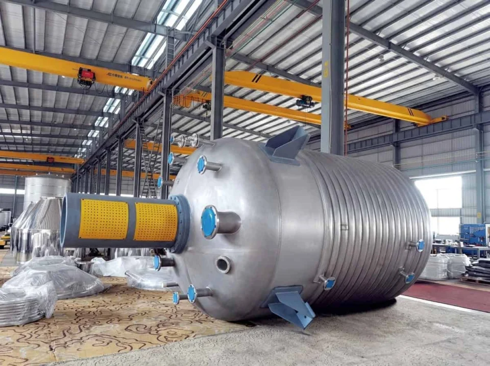
Industrial high pressure reactor manufactured by ChannelVessel
Engineering Capability

High Pressure Reactor Capabilities at a Glance

ChannelVessel engineers high pressure reactors around the complete process envelope rather than a single pressure rating. Capacity, pressure, temperature, materials, agitation, heat transfer and process control are evaluated together to define a practical reactor configuration.

50–20,000 L Custom reactor capacity
Up to 250 bar Industrial high-pressure designs within suitable vessel sizes
Up to 300 bar Special high-pressure configurations subject to engineering review
Engineering Parameter
Available Capability
Capacity
50–20,000 L custom reactor configurations
Pressure
Industrial designs up to 250 bar; special configurations up to 300 bar
Temperature
-20°C to 300°C typical industrial range; special designs up to 500°C
Wetted Materials
304/304L, 316/316L, Duplex 2205/2507, Hastelloy, Titanium and nickel alloys
Process Phases
Liquid, liquid–liquid, gas–liquid and gas–liquid–solid
Agitation
Anchor, paddle, frame, turbine, propeller or custom impeller configurations selected around the mixing duty
Agitator Speed
Typically 30–1500 rpm depending on reactor scale and process duty; special high-speed configurations can be evaluated
Drive & Sealing
Mechanical-seal and magnetic-drive configurations
Heating
Steam, electric or thermal-oil systems
Cooling
Cooling water, chilled water or thermal-fluid systems
Heat Transfer
Jacket, half-pipe coil, internal coil or external circulation
Process Gas Service
H₂, N₂, CO₂ and other compatible process gases
Control
PID, PLC and automated process-control configurations
Inspection & Documentation
NDE, pressure testing, material traceability and project documentation as required
Capability Envelope

Maximum pressure, temperature and volume are not independent ratings. Final capability depends on their combination, construction material, reactor geometry, agitation loads, process medium and applicable design requirements. For applications outside the ranges shown above, send the required operating conditions for an engineering review.

Define the Process First

A High Pressure Reactor Starts With the Design Basis

A high pressure reactor cannot be defined by vessel volume and pressure rating alone. Two reactors with the same nominal capacity and pressure may require very different vessel construction, agitation, sealing, heat-transfer and protection systems depending on temperature, chemistry, reaction behavior and operating cycle. A complete pressure vessel design basis should define the process conditions that the equipment must safely contain and control before detailed reactor configuration begins.

Illustrative RFQ Example The same starting request can lead to very different reactor designs.
5,000 L Nominal volume
100 bar Requested pressure
Process Condition A

Stable Liquid-Phase Duty

Consider a process with relatively stable pressure, moderate temperature, low-to-medium viscosity and no continuous gas demand. The reactor may mainly need reliable circulation, temperature uniformity and material compatibility.

Reaction behavior Relatively stable liquid-phase operation
Mixing demand Bulk circulation and thermal uniformity
Thermal duty Moderate heating and cooling demand
Design emphasis Materials, circulation, temperature control and pressure containment
Process Condition B

Gas-Fed Exothermic Duty

Now consider the same nominal volume and pressure with gas addition, catalyst solids, significant reaction heat and repeated pressurization. The vessel rating may look similar, but the process system becomes a very different engineering problem.

Reaction behavior Gas-consuming, heat-generating multiphase reaction
Mixing demand Gas dispersion plus catalyst suspension
Thermal duty High heat-removal requirement during reaction
Design emphasis Mass transfer, torque, sealing, gas handling, heat removal and pressure control
The volume and pressure did not change. The reaction conditions did—and that can change the agitator, sealing system, thermal configuration, materials, instrumentation and protection strategy.

What Changes the Reactor Design?

These process inputs should be defined before detailed mechanical configuration begins. They are related, but each changes a different part of the reactor design.

Normal Operating Conditions

Define the pressure, temperature, working volume, fluid phases, viscosity and operating sequence expected during stable production. These conditions establish the normal process window from which the reactor configuration begins.

Maximum Credible Process Conditions

The reactor must also account for conditions that may occur during charging, heating, gas addition, reaction, cooling or abnormal operation. Pressure rise, vapor generation, thermal expansion and restricted flow can create conditions different from normal production.

Reaction Behavior

Exothermic, gas-consuming, gas-generating and phase-changing reactions can place very different demands on agitation, pressure control and heat removal. Understanding how the reaction behaves is therefore as important as knowing the target operating pressure.

Process Chemistry

Material compatibility depends on more than the chemical name. Concentration, temperature, water content, impurities, gas composition, cleaning chemicals and exposure time can all affect material selection.

Operating Cycle

A reactor repeatedly heated, cooled, pressurized and depressurized may require different engineering consideration from equipment operating under relatively stable conditions. Batch frequency and expected service life should therefore be considered during the design review.

System Boundary

The Reactor Body Is Only Part of the Pressure System

Nozzles, valves, agitator drive, shaft sealing, instruments, gas lines, thermal utilities, pressure-control equipment and relief devices all interact with the vessel during operation. They should be reviewed as part of the same process system rather than treated as isolated accessories.

Specify the process first. Select the reactor configuration second.
Reactor Configuration

Choose the Reactor Around the Reaction

High pressure reactor configuration should be selected from the reaction phases, viscosity, gas demand, catalyst behavior, heat release and mixing objective—not from pressure rating alone. A reactor that performs well for a simple liquid-phase batch may be unsuitable for a gas-consuming catalytic reaction or a high-viscosity polymerization process even when pressure and temperature are similar.

Gas–Liquid Reactions

Gas–liquid processes depend on how effectively the gas phase is introduced, dispersed and transferred into the liquid. Hydrogenation and other gas-fed reactions may require stable pressure control, suitable gas introduction and agitation capable of generating sufficient gas–liquid contact.

What the Reactor Must Do
Maintain gas–liquid contact Disperse gas through the liquid phase Control pressure as gas is consumed or added Remove reaction heat where required
Engineering Focus
Gas Introduction Agitation Intensity Mass Transfer Pressure Control
Configuration Direction

A stirred high pressure reactor with appropriate gas introduction, agitation and pressure-control arrangements. For mixing-intensive duties, see our agitated reactors.

Liquid–Liquid Reactions

Immiscible or partially miscible liquid phases require sufficient circulation and interfacial area to achieve the desired reaction rate. Density difference and viscosity can strongly influence the required impeller configuration and mixing intensity.

What the Reactor Must Do
Circulate both liquid phases Create sufficient phase dispersion Reduce stagnant regions Maintain thermal uniformity
Engineering Focus
Impeller Geometry Mixing Intensity Viscosity Density Difference
Configuration Direction

A stirred reactor configuration selected around phase dispersion, viscosity and required circulation rather than agitator speed alone.

Gas–Liquid–Solid Reactions

These systems must often suspend a solid catalyst while simultaneously dispersing a process gas. A reactor that can suspend solids is not automatically optimized for gas–liquid mass transfer, so both duties must be considered together.

What the Reactor Must Do
Keep catalyst or solids suspended Disperse process gas effectively Maintain bulk circulation Control reaction heat
Engineering Focus
Catalyst Loading Particle Size Gas Dispersion Torque Mass Transfer
Configuration Direction

A custom stirred reactor arrangement balancing solids suspension, gas dispersion, torque and heat removal. Related process configurations are also covered in our chemical reactors.

High-Viscosity & Polymerization Reactions

Viscosity may increase significantly during the batch, changing the required mixing regime and increasing agitator torque. Heat removal can also become more difficult as circulation decreases and material begins to foul the vessel wall.

What the Reactor Must Do
Maintain circulation as viscosity rises Provide sufficient agitator torque Reduce stagnant regions Remove reaction heat effectively
Engineering Focus
Torque Impeller Geometry Heat-Transfer Area Wall Fouling
Configuration Direction

A high-torque stirred reactor with a thermal-control arrangement selected around viscosity change and heat-removal duty. For processes where jacket performance is critical, see our jacketed reactors.

Semi-Batch & Controlled-Feed Reactions

Reactants may be added gradually to control reaction rate, pressure rise or heat generation. The feed system therefore becomes part of the reactor-control strategy rather than a separate accessory.

What the Reactor Must Do
Control liquid or gas addition Maintain pressure stability Remove heat generated during dosing Respond to changing reaction conditions
Engineering Focus
Feed Rate Pressure Control Temperature Control Batch Automation
Configuration Direction

A reactor system integrating feed control, thermal control and pressure management around the batch sequence. For fully tailored process arrangements, see our custom reactor vessels.

One Pressure Rating — Different Reactor Designs

The same pressure and temperature can require very different reactor configurations depending on what phases must contact each other, how viscosity changes during the batch, how much heat must be removed and how reactants are introduced. Select the reaction duty first. Configure the reactor around it.

Pressure & Temperature

Pressure and Temperature Must Be Evaluated Together

A pressure rating by itself does not fully define a high pressure reactor. The pressure-containing design must be evaluated together with temperature, construction material, vessel geometry and the applicable mechanical design basis. A reactor specified only as “100 bar” can represent very different engineering conditions depending on whether that pressure occurs at moderate temperature or during elevated-temperature chemical service.

Pressure and temperature relationship for high pressure reactor design

Conceptual engineering relationship only. The diagram does not represent an allowable operating envelope, material limit or design curve for a specific reactor.

Working Pressure

The pressure expected during normal process operation. It is an operating condition and should not automatically be treated as the final mechanical design pressure.

Design Pressure

The pressure basis used when evaluating the pressure-containing equipment after the required operating envelope and relevant process conditions have been defined.

MAWP

Maximum Allowable Working Pressure is associated with the completed pressure-containing design under the applicable design rules, not simply a pressure value selected in advance.

Design Temperature

The temperature condition considered with pressure during mechanical design. It can influence material properties, corrosion behavior and thermal expansion.

Why “100 bar” Alone Is Not a Complete Specification

As design temperature changes, the mechanical properties used in pressure design can also change. Vessel diameter, wall thickness, nozzle geometry, corrosion allowance, weld details and material selection further influence the completed pressure boundary.

100 bar at one temperature should not automatically be treated as equivalent to 100 bar at another temperature. The same nominal pressure can lead to a different vessel material, wall thickness, nozzle design, sealing arrangement, inspection scope and thermal configuration when temperature and service conditions change.

Normal operating pressure, maximum process pressure and mechanical design pressure are related, but they should not automatically be treated as the same value.

Pressure Unit Reference
1 MPa 10 bar
10 MPa 100 bar
25 MPa 250 bar
30 MPa 300 bar
Engineering Principle Pressure rating should be the result of a complete design basis—not the starting point of a catalog search.

For non-reacting pressure equipment designed primarily for pressure containment, see our High Pressure Vessels.

Materials Engineering

Select Reactor Materials From the Chemistry, Not the Pressure Alone

Higher pressure does not automatically require a more corrosion-resistant alloy. Material selection begins with process chemistry and then considers temperature, mechanical properties, fabrication, welding, contamination requirements and expected service life. A reliable pressure vessel material selection review should therefore start with the actual process environment rather than selecting an alloy from pressure rating or chemical name alone.

What Actually Drives Material Selection?

The material cannot be selected from chemical name or pressure rating alone. The complete process environment determines whether a material is suitable.

Process Chemistry Chemical composition and reaction environment establish the basic compatibility requirement.
Concentration & Impurities Water content, contaminants and concentration can significantly change corrosion behavior.
Temperature A material suitable at one temperature may perform differently as temperature increases.
Mechanical Requirements Pressure, temperature and geometry determine the mechanical role of the selected material.
Fabrication & Cleaning Welding, surface finish, cleaning chemistry and contamination limits affect the final choice.
Why It May Be Selected

Established fabrication practice, broad availability and suitability for many non-aggressive process environments.

What Must Be Checked

Process chemistry, operating temperature, cleaning media, contamination requirements and expected corrosion.

Engineering Point

Higher pressure alone is not a reason to replace 304L with a more highly alloyed corrosion-resistant material.

Why It May Be Selected

Useful corrosion resistance combined with established fabrication, welding and polishing practices for many process environments.

What Must Be Checked

Chemical concentration, chlorides, temperature, crevice conditions, cleaning chemistry and contamination requirements.

Engineering Point

316L should not be treated as universally suitable for chloride-containing, acidic or elevated-temperature corrosive service.

Why It May Be Selected

Duplex stainless steels can provide a useful combination of mechanical strength and corrosion resistance for selected services.

What Must Be Checked

Chloride exposure, process temperature, welding procedures, fabrication control and the required inspection scope.

Engineering Point

Higher strength does not remove the need to verify chemical compatibility, fabrication limits and service temperature.

Why It May Be Selected

Nickel-based alloys can be evaluated for aggressive acids, mixed chemical environments and selected high-temperature corrosion conditions.

What Must Be Checked

Acid type, concentration, contaminants, reducing or oxidizing conditions, temperature and fabrication requirements.

Engineering Point

The specific alloy grade must be matched to the actual chemistry rather than treating “Hastelloy” as one universal material.

Why It May Be Selected

Titanium can provide strong corrosion performance in specific oxidizing and chloride-containing environments.

What Must Be Checked

Exact process chemistry, operating temperature, reducing conditions, hydrogen-related service and fabrication requirements.

Engineering Point

Titanium should be selected from a verified compatibility review rather than from a general assumption that it is always more corrosion resistant.

Why It May Be Selected

Clad construction can provide corrosion resistance at the process surface while retaining a structural backing material for the pressure boundary.

What Must Be Checked

Cladding method, bonding integrity, weld transitions, nozzle details, lining continuity and inspection requirements.

Engineering Point

Clad construction can be useful where solid high-alloy construction is technically unnecessary or economically inefficient.

Better Material Data

“The Medium Is Acidic” Is Not Enough

“The reactor handles hydrochloric acid.”

A chemical name alone rarely provides enough information for reliable material selection. A material that performs acceptably at one concentration and temperature can behave very differently under another combination.

Concentration
Operating Temperature
Water Content
Impurities
Other Chemicals Present
Gas Composition
Cleaning Chemistry
Expected Exposure Time
Engineering Principle Select the material from chemistry first, then verify that it also satisfies the mechanical and fabrication requirements of the high pressure reactor.
Agitation & Sealing

Agitation Under Pressure: Magnetic Drive or Mechanical Seal?

Agitation becomes part of the pressure-boundary problem when a rotating shaft must transmit torque into a pressurized reactor. Drive and sealing selection should therefore consider pressure, temperature, process containment, torque, speed, viscosity, solids and maintenance requirements together.

Magnetic Drive

A magnetic coupling can transmit agitator torque without a conventional rotating shaft passing directly through a dynamic shaft seal at the reactor pressure boundary. This can be attractive where process containment is a major design objective.

Containment

Removing the conventional dynamic shaft penetration can reduce one potential leakage path, although the complete drive assembly still requires proper mechanical and thermal design.

Torque

The coupling must be sized for the actual agitator torque rather than motor power or RPM alone. Viscosity, impeller diameter, gas dispersion and solids loading can significantly change the required torque.

Temperature

Magnetic materials, bearings and containment components can impose temperature limits that must be evaluated together with pressure.

Solids & Slurry Service

Catalysts or suspended solids can affect internal bearings, circulation and required torque, so slurry service requires more than simply specifying a magnetic coupling.

High pressure reactor agitator drive, shaft sealing and internal mixing structure

Mechanical Seal

Mechanical-seal systems allow the agitator shaft to pass through the reactor head while maintaining process containment through the selected sealing arrangement. They are commonly evaluated where shaft size, torque, process duty or equipment scale favors a conventional rotating shaft arrangement.

Industrial Torque

Mechanical-seal arrangements can be suitable for demanding industrial torque and larger shaft configurations where the complete drive train is designed accordingly.

Seal Arrangement

Single, double or barrier-fluid arrangements may be considered depending on pressure, temperature, medium and containment requirements.

Process Compatibility

Seal faces, elastomers and barrier or flushing fluids must be compatible with the process medium and operating conditions.

Maintenance

Mechanical seals are service components, so inspection access, replacement requirements and maintenance strategy should be considered during reactor layout.

Magnetic Drive or Mechanical Seal?

The correct choice depends on the complete mixing duty rather than one individual specification. A process with low leakage tolerance may strongly favor a magnetic-drive arrangement, while a large industrial reactor with demanding torque may lead to a different solution. Pressure alone does not decide the drive system.

Mixing Principle

Do Not Select an Agitator by RPM Alone

Two high pressure reactors operating at the same agitator speed can deliver very different mixing performance. Impeller type, impeller diameter, reactor diameter, liquid height, viscosity, density, gas flow, solids concentration, motor characteristics and required torque all influence the actual mixing duty. RPM describes rotational speed. It does not describe mixing performance by itself.

Scale-Up Engineering

Scaling a High Pressure Reactor Is Not Simply Increasing Vessel Volume

A reactor cannot be scaled reliably by multiplying vessel volume while keeping the same pressure, temperature and RPM. As reactor diameter and working volume increase, mixing intensity, agitator torque, gas–liquid mass transfer and heat-transfer area do not scale at the same rate. This is why a successful pilot reaction may behave differently after transfer to a larger production reactor even when the nominal operating conditions appear unchanged.

Same Pressure + Same Temperature + Same RPM ≠ Same Reactor Performance
Tip Speed π × D × N D = impeller diameter
N = rotational speed

What It Tells You

Tip speed describes how fast the outer edge of the impeller moves through the fluid. It changes with both impeller diameter and rotational speed.

Scale-Up Implication

If impeller diameter increases while RPM remains unchanged, tip speed increases. Maintaining the same RPM does not maintain the same tip speed.

Power per Unit Volume P / V P = agitator power
V = working volume

What It Tells You

Power per unit volume is commonly used when comparing mixing intensity between reactor scales. It relates agitator power to the amount of process fluid being mixed.

Scale-Up Implication

Maintaining the same P/V and maintaining the same tip speed are different scale-up strategies and can produce different circulation, shear and mixing conditions.

Gas–Liquid Mass Transfer kLa Volumetric gas–liquid mass-transfer capability

What It Tells You

For hydrogenation and other gas-fed reactions, reactor performance may depend strongly on how effectively gas is transferred into the liquid phase rather than on pressure alone.

Scale-Up Implication

kLa can change with agitation, gas flow, impeller configuration, pressure, viscosity and fluid properties. The same RPM and pressure do not guarantee the same gas–liquid mass-transfer performance after scale-up.

Heat-Transfer Area per Volume A / V A = available heat-transfer area
V = working volume

What It Tells You

A/V compares the heat-transfer area available to the amount of reacting material that must be heated or cooled.

Scale-Up Implication

For geometrically similar vessels, volume increases faster than external surface area. A/V therefore generally decreases as reactor size increases, so a reaction that is easy to cool at pilot scale may become heat-transfer limited in production.

Mechanical Consequence

Torque Also Changes the Design Problem

Motor power, rotational speed and torque are related but not interchangeable. Larger impellers, higher viscosity, gas dispersion and solids suspension can significantly increase shaft torque, which then affects the agitator shaft, drive, sealing system and reactor mechanical design.

There Is No Single Universal Scale-Up Rule

Some processes are scaled primarily around mixing intensity. Others depend more strongly on tip speed, gas–liquid mass transfer, solids suspension, circulation or heat removal. The correct scale-up criterion should therefore come from the reaction duty rather than from one universal formula.

Thermal Management

Heat Removal Can Become the Real Limit of Reactor Scale-Up

As reactor scale increases, thermal design becomes a process-performance issue rather than simply a utility connection problem. A high pressure reactor may be capable of reaching the required reaction temperature but still be unable to remove heat fast enough during an exothermic reaction. For hydrogenation, polymerization, oxidation and other heat-generating processes, the thermal system should be evaluated from the expected reaction duty rather than selected only from the desired operating temperature.
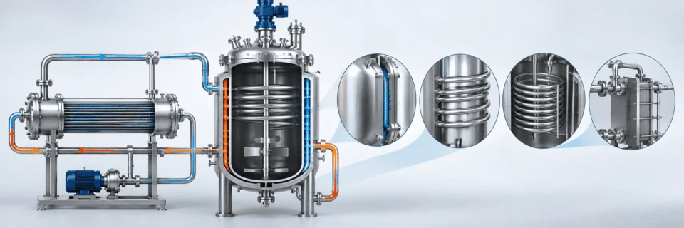
High pressure reactor thermal management with jacket, internal coil and external circulation heat exchanger
Q = U × A × ΔT
Increasing utility temperature difference alone does not guarantee sufficient thermal performance. Heat transfer is also affected by available area, fluid circulation, viscosity, fouling, utility conditions and the reactor-side heat-transfer coefficient.
Q = heat-transfer rate U = overall heat-transfer coefficient A = available heat-transfer area ΔT = effective temperature difference

Thermal-Control Configurations

The best arrangement depends on required duty, reactor scale, utility conditions, process viscosity, fouling tendency and cleaning requirements.

Full Jacket

A conventional jacket uses the external vessel wall as the primary heat-transfer surface. It can be effective when available area, utility flow and temperature difference are sufficient for the required duty. For processes where jacket configuration is a primary design feature, see our Jacketed Reactors.

Half-Pipe / External Coil

A half-pipe or external coil creates a defined utility flow path around the reactor shell and can be evaluated where utility pressure, flow distribution or thermal duty makes a conventional jacket less suitable.

Internal Coil

An internal coil adds heat-transfer surface inside the reactor, but it also occupies process volume and can influence mixing, solids movement, fouling and cleaning.

External Circulation

Where the vessel jacket alone cannot provide sufficient thermal duty, an external circulation loop and heat exchanger can be evaluated together with pumpability, viscosity, solids, pressure drop, residence time and cleaning.

Thermal Design Question

The Question Is Not Only “Can It Heat Up?” Can It Remove Heat Fast Enough?

A reactor that reaches its target temperature during startup may still be unable to control temperature once an exothermic reaction begins. The more important question is whether the thermal system can remove heat as fast as the reaction generates it.

Thermal Design Inputs

These inputs provide a more useful basis for evaluating the heating and cooling system than reactor volume or target temperature alone.

Reaction Side

Reaction heat Batch mass Viscosity Expected heat-generation profile Maximum allowable temperature rise

Utility Side

Steam pressure and temperature Thermal-oil temperature Cooling-water inlet temperature Chilled-fluid temperature Available utility flow

Performance Target

Required heat-up time Required cooldown time Maximum batch temperature Required temperature stability Allowable process variation
Engineering Principle Thermal-control equipment should be selected from the actual heating and heat-removal duty, not from reactor volume or operating temperature alone.
Gas Handling & Process Control

Gas Charging, Dispersion and Pressure Control Need Their Own Design

A high pressure reactor using hydrogen, nitrogen, carbon dioxide or another process gas needs more than a gas connection on the vessel head. Gas supply pressure, regulation, isolation, introduction method, agitation, pressure control, venting and sampling should be evaluated as one operating system around the required reaction conditions.

Gas Supply

Source pressure, flow, composition and purity define the starting conditions.

Pressure Regulation

The gas source is matched to the pressure and flow required downstream.

Isolation & Non-Return

Isolation and reverse-flow protection help separate reactor contents from upstream gas equipment.

Reactor Entry

Headspace charging, dip tube or sparger arrangements are selected around the process.

Pressure Control

Gas feed and outlet control respond to reaction behavior and gas consumption.

Vent / Recovery

Outlet gas may be discharged, recovered, recycled or routed to downstream treatment.

Supply Conditions

Gas Supply & Pressure Regulation

The gas source must provide sufficient pressure and flow for the required reactor conditions. Useful design inputs include source pressure, available flow, gas composition, purity and whether the process uses batch charging or continuous addition.

A high-pressure source should be matched to a suitable regulation arrangement before entering the reactor system. Regulator range, inlet pressure, outlet pressure, expected flow and downstream equipment ratings all influence the design.

Source Pressure Available Flow Gas Purity Gas Composition Batch or Continuous Feed
Reactor Entry

How the Gas Enters the Reaction

Gas can enter through the reactor headspace, a dip tube below the liquid surface or a sparger designed to distribute the gas through multiple openings. The correct arrangement depends on whether the process needs simple pressurization, inerting or active gas–liquid mass transfer.

The introduction method should be evaluated together with agitation because a sparger alone does not guarantee sufficient gas–liquid contact or reaction performance.

Headspace Charging Dip Tube Sparger Agitation Interaction
During Reaction

Pressure Control Must Follow Reaction Behavior

Gas-consuming reactions such as hydrogenation can cause reactor pressure to fall as gas is absorbed and consumed. Depending on the process, the control strategy may maintain relatively constant pressure or follow a defined pressure profile.

Normal pressure control can involve gas feed control, pressure measurement, outlet control or back-pressure regulation. The required arrangement should therefore be defined from the reaction behavior rather than treated only as an instrumentation detail.

Gas Feed Control Pressure Measurement Back-Pressure Control Controlled Pressure Profile
Outlet Path

Vent, Recovery or Recycle

Outlet gas may be discharged, recovered, recycled or sent to downstream treatment depending on the process. The required destination should be defined early because it influences piping, pressure control and auxiliary equipment.

Operating Sequence

Purging and Inerting Are Part of the Process

Processes involving flammable, reactive or oxygen-sensitive media may require a defined purge and inerting strategy before process gas is introduced. The reactor, connected piping and gas-handling equipment should therefore be considered as one system when the operating sequence is developed.

Sampling

Sampling Is Also a Pressure-Boundary Decision

If process samples must be taken while the reactor remains pressurized, the sampling arrangement should be defined during design rather than added after fabrication. Sampling can affect isolation, cooling, depressurization, line volume, plugging risk and operator exposure.

Engineering Principle Gas handling should be designed around the complete process path—from supply pressure to reactor entry, gas–liquid contact, pressure control and outlet destination.

Where gas regulation, dosing, instrumentation and auxiliary equipment need to be integrated on a common frame, see our Process Skid Systems.

Safety Architecture

High Pressure Reactor Safety Is a System — Not a Single Relief Valve

Pressure relief is essential, but a high pressure reactor requires more than one protective device. Safe reactor operation depends on measurement, control, interlocks, overpressure protection, utility reliability and a defined response to abnormal process conditions. Mechanical pressure containment and reaction-process safety are related—but they are not the same engineering problem.

Measurement

Detect the Process Condition

Reliable protection begins with knowing what the reactor is actually doing during operation.

Pressure Measurement Pressure data supports normal control, alarms and defined high-pressure responses.
Temperature Measurement In some exothermic reactions, temperature can begin rising before a significant pressure increase is observed.
Core Process

The Reaction Creates the Hazard

The protection system must detect and respond to the actual process conditions rather than treating the reactor only as a pressure-containing vessel.

Pressure Temperature Reaction Rate Agitation Heat Removal
Control & Interlocks

Respond Before the Condition Escalates

Defined process limits can initiate protective actions according to the project control philosophy.

High-Pressure Interlock Can be configured to stop feed, isolate a source or initiate another defined protective response.
High-Temperature Interlock Can initiate actions such as stopping heating or reactant addition and moving the process toward a defined safer condition.
Agitation Monitoring Loss of mixing can reduce gas dispersion, allow solids to settle and decrease heat-transfer performance.
Pressure Relief

Provide a Defined Overpressure Path

Pressure-relief protection may involve a safety valve, rupture disc or an engineered combination depending on service and applicable requirements.

Safety Valve / Rupture Disc The device selection and relief path should be evaluated from the credible overpressure scenarios rather than vessel pressure rating alone.
International Reference The ISO 4126 series covers safety devices for protection against excessive pressure, including safety valves and bursting-disc devices.
Emergency Response

Define the Safer System State

Emergency response should consider the complete reactor system rather than simply stopping one item of equipment.

Cooling Failure For an exothermic reaction, loss of heat removal can be more important than temporary loss of heating.
Emergency Shutdown The shutdown philosophy should define the intended state of gas feed, liquid feed, heating, cooling, agitation, pressure control and the vent or recovery path.

Relief Protection Starts With Credible Scenarios

Relief-device selection and sizing should begin with the abnormal conditions that can realistically create overpressure in the specific process, not simply with reactor MAWP.

Blocked Outlet
Excessive Gas Addition
Vapor Generation
External Heating
Reaction Runaway
Utility or Control Failure
Protection Philosophy

The Pressure Vessel Is Only One Protection Layer

A strong reactor design combines the mechanical pressure boundary with process measurement, control, interlocks, relief protection and a defined emergency response.

For broader pressure-vessel code and compliance considerations, see our Codes & Standards resource.

Code, Fabrication & Inspection

Code Compliance Starts With the Design Basis

The applicable pressure-vessel code, project specification and inspection scope should be defined before detailed fabrication begins. A high pressure reactor should not be assigned a code or inspection plan simply because it is described as “high pressure.” The final manufacturing basis depends on the pressure–temperature combination, construction material, service conditions, jurisdiction, purchaser requirements and the documentation expected at project handover.
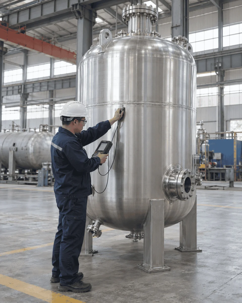
High pressure reactor fabrication and ultrasonic inspection in a pressure vessel workshop
Manufacturing Evidence Inspection should be planned before fabrication begins.

Material traceability, welding records, NDE, pressure testing and final documentation are stronger when they are defined as part of the project inspection plan rather than assembled after completion.

Design Basis

Applicable Code & Project Requirements

The applicable code should be selected from the actual project conditions and jurisdiction. “High pressure” does not automatically mean that every reactor should be designed to the same ASME Division.

The ASME Boiler and Pressure Vessel Code includes Section VIII Division 1 and Division 3, but the appropriate basis must be determined from the specific project rather than the equipment name alone.

Traceability

Material Identity Must Survive Fabrication

Correct material selection has little value if material identity is lost during cutting, forming or fabrication. Material certificates, heat or lot identification and traceability should therefore follow the pressure-retaining material through the required manufacturing stages.

Material Certificates Heat / Lot Identification PMI Where Specified Weld Consumable Control
Welding Control

Qualified Procedures for Pressure-Retaining Joints

Pressure-retaining welds should be produced under the qualified procedures required by the applicable project basis. Welding control can include WPS, PQR, welder qualification, joint preparation, fit-up, heat-input control and weld traceability.

WPS PQR Welder Qualification Fit-Up Weld Traceability
Nondestructive Examination

Inspection Method Depends on the Joint and Material

The required NDE method and extent depend on material, weld type, code requirements and the project inspection plan. RT and UT can be applied to suitable volumetric weld examination, while PT or MT may be used for appropriate surface examination.

RT UT PT MT PMI Where Required
Pressure Testing

Test Conditions Come From the Design Basis

The completed pressure-containing equipment is tested according to the applicable design and inspection requirements. Hydrostatic testing is commonly used, while pneumatic testing may be considered where appropriate and permitted by the project basis.

Test method, pressure, medium and acceptance criteria should come from the applicable requirements rather than from a universal multiplier copied from another reactor.

Final Inspection

Confirm the Equipment That Will Actually Be Delivered

Final inspection should verify the fabricated equipment against the approved project requirements before shipment. This can include nozzle orientation, overall dimensions, support locations, agitator alignment, flange orientation, surface condition, marking and final visual inspection.

Nozzle Orientation Dimensions Supports Agitator Alignment Final Visual Inspection

Documentation Dossier

The final documentation package should be agreed before fabrication begins. Inspection records that were never planned cannot always be recreated after the reactor is complete.

Approved Drawings
Material Records
Welding Records
NDE Reports
Pressure-Test Records
Inspection Reports
Instrument Data
Final Manufacturing Documentation
Related Technical Resources Code compliance is strongest when design, fabrication, inspection and documentation are planned as one project scope.

Read more about Codes & Standards, Fabrication & Welding and Inspection & Testing.

Industrial Applications

Where High Pressure Reactors Are Used

High pressure reactors are used where reaction performance depends on controlled pressure, temperature, gas–liquid contact, catalyst behavior, material compatibility or precise thermal management. The reactor configuration may look similar from the outside, but the engineering priorities can change significantly between chemical, petrochemical, pharmaceutical and emerging-energy processes.

Chemical industry high pressure reactor applications
Chemical Processing

Chemical Processing

High pressure reactors are used for catalytic reactions, hydrogenation, gas–liquid synthesis and specialty chemical production where pressure, mixing and thermal control must work together.

Engineering Focus Pressure control · Material compatibility · Agitation · Heat removal
View Chemical Industry
Petrochemical high pressure reactor applications
Petrochemical

Petrochemical Processing

Petrochemical reactions can combine elevated pressure, temperature, process gases and demanding inspection requirements, making the complete pressure–temperature design basis critical.

Engineering Focus Pressure–temperature design · Gas handling · Materials · Inspection
View Petrochemical Industry
Pharmaceutical and fine chemical high pressure reactor applications
Pharmaceutical

Pharmaceutical & Fine Chemical Synthesis

Batch repeatability, process containment, material compatibility and controlled addition can be as important as pressure rating itself in pharmaceutical and fine-chemical reaction systems.
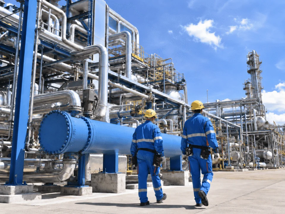
Engineering Focus Containment · Cleaning · Dosing · Repeatability
View Pharmaceutical Industry
Oil and gas high pressure process reactor applications
Oil & Gas

Oil & Gas Process Applications

High-pressure reaction and process equipment can be required for gas-service, catalytic and specialty process duties where containment and corrosion resistance are critical.

Engineering Focus Gas service · Corrosion · Pressure containment · Inspection
View Oil & Gas Industry
New energy and advanced materials high pressure reactor applications
New Energy

New Energy & Advanced Materials

Emerging material and energy processes can require custom combinations of pressure, temperature, gas atmosphere and corrosion-resistant construction materials.

Engineering Focus Atmosphere control · Materials · Thermal control · Custom instrumentation
View New Energy Industry
Custom industrial reactor engineering and project fabrication
Pilot to Production

Pilot & Custom Industrial Processes

Processes moving from pilot scale to production often require a reactor engineered around actual process data rather than a fixed catalog configuration.

Engineering Focus Scale-up · Custom internals · Process integration · Documentation
View Custom Reactor Vessels
Prepare Your RFQ

What We Need to Engineer Your High Pressure Reactor

A better RFQ produces a better reactor proposal. You do not need to have every design detail finalized before contacting us, but the information below can significantly improve the first engineering review and reduce quotation assumptions. If you only have a process description, required volume, pressure, temperature and medium, send those first.

Minimum Information to Start

Core Information Ready: 0/6
These inputs are usually enough to begin a preliminary technical discussion. Click the items you already have prepared.

For a More Accurate Engineering Review

The more complete the operating data, the fewer assumptions are needed when evaluating reactor configuration, materials, agitation, thermal control, gas handling and project documentation.

Process

Define what is inside the reactor and how the batch operates.

Batch or semi-batch operation
Total batch size
Working volume
Liquid phases
Gas phase
Solids or catalyst
Density
Viscosity

Pressure & Temperature

Define normal operation and the required operating envelope.

Normal operating pressure
Maximum expected operating pressure
Design pressure if already defined
Vacuum condition if applicable
Operating temperature
Design temperature if defined
Minimum temperature if relevant
Pressure cycling frequency

Chemistry

Provide enough information to review material compatibility.

Process chemicals
Concentration
Gas composition
Catalyst
Impurities
Corrosion concerns
Known incompatible materials
Cleaning chemistry if relevant

Agitation

Describe the mixing duty rather than specifying RPM alone.

Viscosity range
Solids loading
Gas-dispersion requirement
Existing impeller information if available
Existing speed range if available
Known torque requirement

Thermal Duty

Define how fast the batch must be heated, cooled and controlled.

Heating utility
Cooling utility
Reaction heat if known
Required heat-up time
Required cooldown time
Maximum permitted batch temperature

Controls & Project Requirements

Define integration, code, inspection and delivery requirements.

Pressure control
Temperature control
Gas-flow control
Liquid-feed control
Batch automation
PLC / DCS interface
Applicable design code
Inspection / NDE requirement
Electrical standard
Hazardous-area requirement
Project destination
Required documentation
You Can Start With Incomplete Data

Send the Process Conditions and Drawings You Already Have

If your reactor datasheet is not complete, send the required volume, process conditions and any available drawings first. The missing engineering inputs can be reviewed before the final reactor configuration and quotation are completed.

High Pressure Reactor FAQ

Frequently Asked Questions

These questions cover the most common engineering and procurement decisions involved in selecting, specifying and scaling a custom high pressure reactor.

What is considered a high pressure reactor?

There is no single universal pressure value that separates every high pressure reactor from a conventional reactor.

In industrial practice, the term generally refers to a reactor specifically engineered for chemical reactions performed under elevated pressure, where pressure containment must be integrated with mixing, temperature control, gas handling, materials and process protection.

What is the difference between working pressure and design pressure?

Working pressure describes the pressure expected during normal process operation.

Design pressure is part of the mechanical design basis and is used when evaluating the pressure-containing equipment. They are related, but they should not automatically be treated as the same value.

What is the difference between a high pressure reactor and an autoclave?

The terms can overlap.

A high pressure reactor usually emphasizes controlled chemical reaction duties involving agitation, heating or cooling, gas handling, instrumentation and process control. “Autoclave” is a broader term that can describe sealed pressure equipment used for chemical reactions, material processing, testing or other pressure-temperature applications.

Should I choose a magnetic drive or a mechanical seal?

Neither option is automatically better for every project.

Selection depends on pressure, temperature, leakage tolerance, agitator torque, shaft size, viscosity, solids, process chemistry and maintenance requirements. Magnetic drive can reduce a conventional rotating shaft penetration, while mechanical-seal arrangements may be more appropriate for some large or high-torque industrial reactor duties.

Which material is best for a high pressure chemical reactor?

Pressure alone does not determine the best material.

Material selection should consider process chemistry, concentration, temperature, impurities, gas phase, cleaning media, fabrication requirements and applicable mechanical design rules. 316L is common in many process applications, but it is not universally suitable.

Can a high pressure reactor use a jacket or internal coil?

Yes.

Heating and cooling can be provided through full jackets, half-pipe coils, internal coils or external circulation systems depending on the required thermal duty. The correct arrangement depends on reactor size, utility conditions, viscosity, heat generation and required heating or cooling rate.

Why can a pilot reaction behave differently after scale-up?

Increasing reactor size changes relationships involving impeller diameter, tip speed, power per unit volume, gas–liquid mass transfer and heat-transfer area per unit volume.

Using the same pressure, temperature and RPM therefore does not guarantee the same reaction behavior at production scale.

Does a higher maximum pressure rating mean a better reactor?

No.

An unnecessarily high pressure rating can increase wall thickness, equipment weight, cost and manufacturing complexity without improving the process. The reactor should be engineered for the actual process design basis with the required margin and applicable code requirements.

What information is needed for a custom high pressure reactor quotation?

The most useful starting information includes working volume, process medium, operating pressure, temperature, reaction type, gas involvement, material requirement, agitation duty, heating and cooling conditions, applicable code and any available drawings or datasheets.

A complete datasheet is not required before the first technical discussion.

Start Your Reactor Project

Start With Your Process Conditions — Not a Catalog Model

A high pressure reactor performs as part of a complete reaction system. Send us your process conditions, datasheet, P&ID or existing drawings. We can review the pressure vessel, materials, agitation, thermal control, gas handling, instrumentation, inspection and fabrication requirements as one engineering scope.

Incomplete project data is acceptable for the first engineering review.
Scroll to Top
DRAWING & FILE REVIEW

Send Your Drawings

Upload your drawings, datasheets or existing specifications. Our engineering team will review the files and respond with technical feedback.

Engineering Review

Drawings, specifications and process requirements

Confidential File Handling

Project files are used only for technical review and quotation

Faster Technical Feedback

Clearer inputs help us respond more accurately and efficiently

DRAWING & FILE REVIEW

Send Your Drawings

Upload your drawings, datasheets or specifications. Our engineering team will review your files and provide technical feedback.

Contact Form Demo (#3)
Project Protected NDA available
12h Response
ASME / PED
AFTER SUBMISSION
01 Review
→
02 Confirm
→
03 Quote
TECHNICAL QUOTATION

Get a
Technical Quote

Tell us what you need. Our engineering team will review your requirements and respond within 12 hours.

Engineered for Your Application

From concept to certified manufacturing

Global Compliance

ASME, PED and other international standards

Expert Support

Direct access to our engineering team

TECHNICAL QUOTATION

Get a Technical Quote

Tell us what you need. Our engineering team will review your requirements and respond within 12 hours.

Contact Form Demo
Project Protected NDA available
12h Response
ASME / PED
AFTER SUBMISSION
01 Review
→
02 Confirm
→
03 Quote