
ChannelVessel Intelligent Equipment Co., Ltd. Contact Us
INTEGRATED PROCESS SYSTEMS

Process Skid Systems

Integrate vessels, pumps, piping, valves, instrumentation and controls into one coordinated process package engineered around your P&ID, operating conditions, available space and site interfaces.

Rather than assembling individual components in the field, a process skid brings the critical equipment together on a common structural frame for controlled fabrication, inspection, testing and installation.

Process Integration
Piping & Valves
Instrumentation & Controls
Factory Assembly & FAT

Process duty, materials, equipment scope, controls and applicable standards are defined according to the actual project requirements.
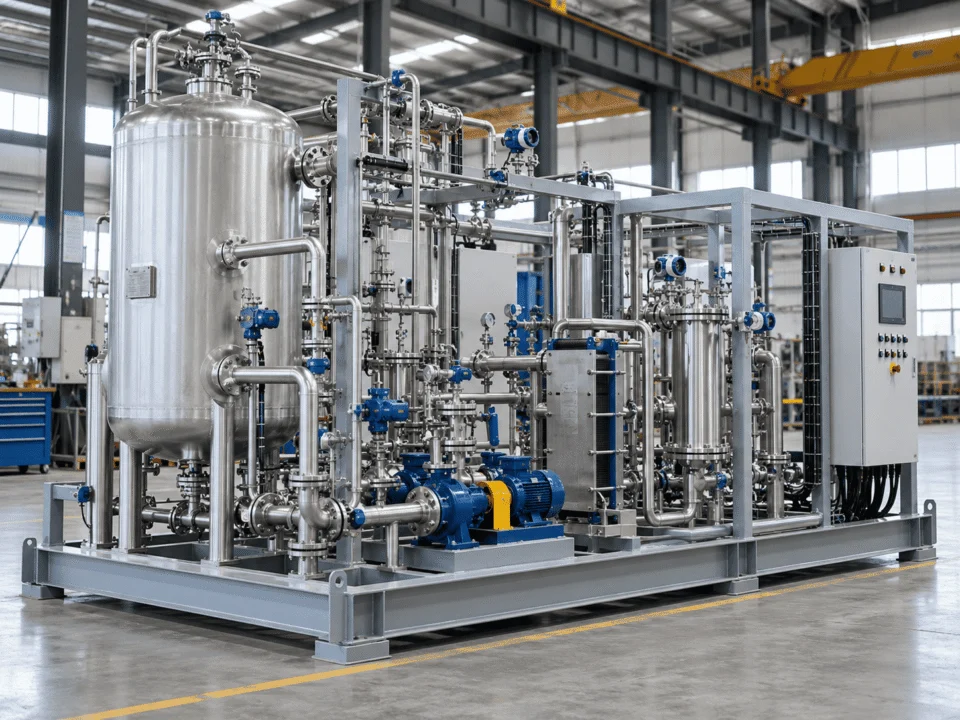
Integrated process skid system with vessels, pumps, piping, valves and instrumentation
SYSTEM INTEGRATION

More Than Equipment Mounted on a Frame

A process skid is not simply a collection of pumps, vessels and valves installed on structural steel. The real engineering task is making every component operate as one coordinated system.
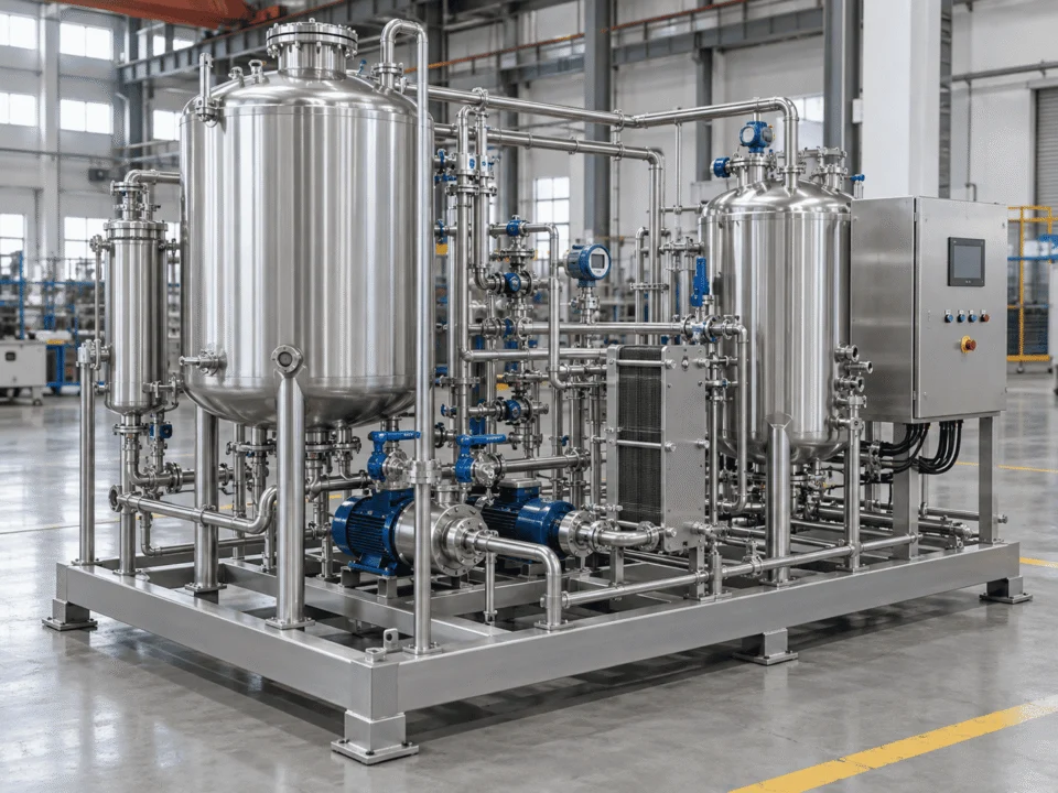
Integrated process skid system showing vessels, piping, pumps, valves and instrumentation
INTEGRATED PACKAGE Process + Mechanical + Controls

Process flow must be translated into equipment selection, piping routes, control logic, maintenance access, utility connections, structural support and clearly defined site interfaces.

Process Equipment

Vessels, tanks, filters, separators, heat exchangers and other equipment selected around the required process duty.

Vessels Tanks Filters Heat Exchangers

Fluid Handling

Pumps, process piping, manifolds, valves, drains, vents and connection points arranged according to required flow, pressure and operating conditions.

Pumps Piping Valves Drains & Vents

Instrumentation

Pressure, temperature, flow, level and other instruments used to monitor and control the process.

Pressure Temperature Flow Level

Controls & Electrical

Local control panels, PLC/HMI systems, junction boxes, field wiring and communication interfaces where included in the project scope.

PLC HMI Panels Field Wiring

Structural Integration

Base frames, equipment supports, pipe supports, lifting provisions and access structures developed around equipment loads, package layout and transport requirements.

Base Frame Equipment Supports Pipe Supports Lifting Provisions
KEY ENGINEERING PRINCIPLE
The objective is not to fit the maximum number of components onto the smallest frame.

The objective is to create a system that can be fabricated, transported, installed, operated and maintained without compromising process performance or accessibility.

Fabricate → Transport → Install → Operate → Maintain
DESIGN BASIS

A Reliable Process Skid Starts With the Design Basis

Selecting components before the process conditions are understood can create problems later in pump sizing, piping, material selection, control philosophy and package layout.

START HERE Define the duty before defining the hardware.

The same process function can require a completely different skid once flow, pressure, temperature, fluid properties, controls or site conditions change.

PROCESS INPUTS

Define How the Process Actually Operates

Process data drives pump selection, piping size, equipment ratings, material compatibility and the overall system arrangement.

Design Input Typical Information Required Main Design Impact
Process Medium Fluid composition, concentration, solids and contaminants Material compatibility, pump and valve selection
Flow Rate Minimum, normal and maximum flow Pump sizing, pipe diameter and control range
Pressure Inlet, outlet, operating and design pressure Equipment rating and piping class
Temperature Minimum, normal and maximum temperature Materials, seals, insulation and instruments
Physical Properties Density, viscosity and phase behavior Pump selection, line sizing and system hydraulics
Allowable Pressure Drop Available system pressure loss or ΔP limit Pipe size, filter selection and valve sizing
BATTERY LIMITS & TIE-INS

Define the System Boundary Before Detailed Engineering

A process skid becomes much easier to install when the limits between the packaged system and the customer's plant are clearly defined early in the project.

ENGINEERING FOCUS Every connection crossing the skid boundary should have a defined owner, condition and location.
SKID BOUNDARY Integrated Process Package

Equipment, piping, valves, instrumentation and controls engineered as one coordinated system.

P&ID GA UTILITY LIST I/O
PROCESS INTERFACES

Define What Enters and Leaves the Skid

Process tie-ins should be fixed before the layout is released so nozzle location, line routing and equipment orientation align with the actual plant connection points.

PROCESS INLET Size · Rating · Condition · Location
PROCESS OUTLET Size · Rating · Required Discharge Condition
RECYCLE / RETURN Flow Path · Connection · Control Requirement
NOZZLE ORIENTATION Direction · Elevation · Flange Standard
A mechanically complete skid can still create field delays if its interfaces do not match the plant.

Nozzle elevations, utility conditions, electrical supply, control ownership and tie-in directions should be confirmed before fabrication is released.

ENGINEERING WORKFLOW

From P&ID to an Integrated Skid Layout

A P&ID defines how the process should function. The skid design must convert that process logic into a physical system that can be fabricated, tested, transported, installed and maintained.

DESIGN OBJECTIVE Translate process intent into a buildable, accessible and transportable package.
STAGE 01

Confirm the Inputs Before Selecting Hardware

Review process conditions, required duty, project specifications, site utilities, installation constraints and the intended scope of supply.

INPUTS Process conditions, utilities, codes, available space and customer requirements
OUTPUT Agreed design basis and clear scope assumptions
CHECK Do the inputs describe the real operating case rather than only the nominal case?
ENGINEERING FOCUS A good skid layout supports the process without creating unnecessary piping complexity or inaccessible equipment.
Short, logical flow paths Reachable valves and instruments Real maintenance clearance Defined site tie-ins
INTEGRATED SCOPE

What Can Be Integrated Into the Skid?

The equipment included in a process skid should follow the process duty rather than a fixed equipment list. A well-defined package integrates only the components required to perform, control and support the process.

SELECTION PRINCIPLE Build the package around the required function — not around a standard bill of materials.

Vessel type, volume, pressure rating, material, nozzle arrangement and internal configuration are selected around the process duty and operating conditions.

Key design inputs: Working volume · Pressure · Temperature · Material compatibility · Nozzle arrangement

Pump type should be selected according to required flow, differential pressure, viscosity, suction conditions, solids content and operating range.

Key design inputs: Flow · Head · NPSH · Viscosity · Solids · Minimum / maximum operating case

Thermal equipment is integrated according to required duty, available utilities, allowable pressure drop and control requirements.

Key design inputs: Heat duty · Inlet / outlet temperatures · Utility conditions · ΔP · Fouling tendency

Filtration and separation equipment should be selected around contaminant loading, required removal efficiency, maintenance frequency and allowable pressure drop.

Key design inputs: Particle / phase characteristics · Loading · Removal target · Pressure drop · Service interval

Piping and valves should support required flow while maintaining accessibility, drainage, venting, support and appropriate material compatibility.

Key design inputs: Line size · Piping class · Valve function · Drain / vent philosophy · Support requirements

Instrumentation and controls can range from local indicators to fully automated packages integrated with the plant DCS or supervisory system.

Key design inputs: Control philosophy · I/O · Alarm / interlock requirements · Communication protocol · Panel scope

Structural design should account for equipment loads, piping loads, lifting conditions, transport loads, maintenance access and final installation conditions.

Key design inputs: Equipment weight · Operating weight · Lifting method · Transport condition · Foundation interface
Only integrate what the process actually needs.

Adding unnecessary equipment increases skid size, piping complexity, procurement cost and maintenance requirements without improving process performance.

Process Duty → Required Function → Equipment Scope
OPERATION & MAINTENANCE

A Compact Skid Still Needs to Be Maintainable

Reducing footprint is useful, but compactness should not come at the expense of safe operation or practical maintenance. Equipment arrangement should consider how operators and maintenance teams will actually interact with the package after installation.

LAYOUT RULE Compact does not mean inaccessible.

A smaller footprint is only an improvement when routine operation, inspection and component removal remain practical.
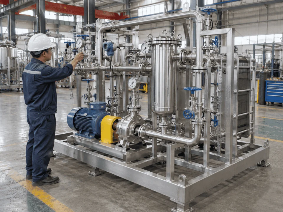
Process skid maintenance access with pumps, valves, instruments and filtration equipment
ACCESS Operate · Inspect · Remove · Replace
MAINTENANCE ACCESS REVIEW

Check the Layout Before It Becomes Difficult to Change

Select a review point to see what should be checked during skid layout development.

VALVE ACCESSIBILITY

Place Routine Controls Where Operators Can Actually Use Them

Frequently operated isolation and control valves should remain visible and reachable from a practical working position. Avoid arrangements where handwheels, actuators or service points are trapped behind piping or structural members.

Reachable operating position Clear handwheel / actuator movement Access without removing adjacent piping
BEFORE APPROVING A COMPACT LAYOUT, ASK:
Can operators reach it?
Can maintenance remove it?
Can the instrument be calibrated?
Can the system be drained?
TRANSPORT & INSTALLATION

Design the Shipping Envelope Before Fabrication Is Complete

The ideal process arrangement is not automatically the ideal shipping arrangement. Package dimensions, total weight, center of gravity, lifting method, transport route and final site access can all affect the skid configuration.
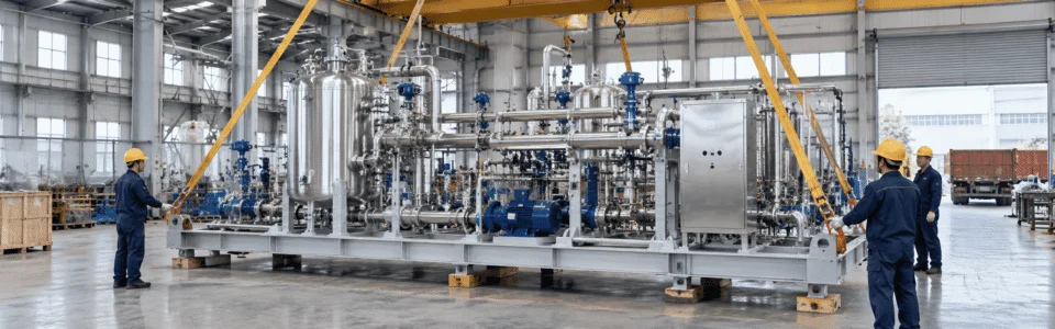
PROJECT RULE Transport and installation constraints should influence the layout before the GA is frozen.
Process skid system prepared for transport and installation with lifting points and factory handling access
DIMENSIONS L × W × H
WEIGHT Dry / Shipping / Operating
LIFTING Points · Method · COG
ACCESS Route · Door · Foundation
SHIPPING ENVELOPE

Know the Maximum Practical Package Size Before the Layout Is Locked

Overall length, width, height and shipping weight should be reviewed together with the planned transport method and route. A layout that performs well in the factory can still create unnecessary logistics problems if transport limits are considered too late.

CHECK Overall L × W × H

Include protruding nozzles, panels, platforms and temporary shipping supports.

CHECK Shipping Weight

Differentiate dry, shipping and operating conditions where relevant.

CHECK Transport Method

Container, flat rack, truck or special transport can change the practical envelope.

CHECK Route Restrictions

Road, bridge, turning radius and delivery-site limitations should be reviewed early.

ENGINEERING DECISION Single skid or multiple modules?

The correct answer depends on process integration, transport restrictions, lifting capability, site access and maintenance requirements.

01 Process Logic
→
02 Transport Limit
→
03 Site Access
→
04 Module Strategy
CODES & STANDARDS

Different Parts of the Skid May Follow Different Requirements

A process skid combines multiple equipment types. The package should therefore be reviewed by scope rather than described as complying with one single code by default.

PROJECT PRINCIPLE Standards should follow the equipment scope, service conditions, destination and customer specification.
PRESSURE VESSEL SCOPE

Apply the Pressure Vessel Code to the Pressure-Containing Equipment It Governs

TYPICAL CONSIDERATION ASME Section VIII or specified project pressure vessel code
WHEN IT MATTERS

Where a vessel is within the jurisdiction of the applicable pressure vessel code or customer specification.

WHAT IT AFFECTS

Design calculations, materials, welding, inspection, testing, documentation and certification scope.

CONFIRM EARLY

Design pressure, design temperature, fluid service, material, code edition, stamping or certification requirement.

CODE SELECTION DEPENDS ON THE PROJECT Confirm the governing requirements during technical clarification.
Project Location
Process Medium
Pressure & Temperature
Equipment Classification
Hazardous Area
Customer Specification
End-User Requirements
Certification Scope
Do not assume the whole skid follows one code.

Different components may be governed by different standards, while some requirements apply only when specifically called for by the project or destination.

MATERIALS & COMPONENT SELECTION

Select Components Around the Service, Not Around a Standard BOM

Using stainless steel throughout the skid does not automatically make the system suitable for every process. Material and component selection should respond to the actual fluid, operating conditions, cleaning requirements and installation environment.

SELECTION LOGIC Process conditions first. Component specification second.
Process Medium
→
Operating Conditions
→
Compatibility & Duty
→
Final Specification
MATERIAL SELECTION

Match Wetted Materials to the Actual Chemical Service

Material choice should reflect corrosion potential, temperature, pressure, cleaning chemicals, solids content and external environment rather than a generic preference for stainless steel.

SELECTION FACTORS
  • Chemical compatibility
  • Corrosion potential
  • Temperature and pressure
  • Chloride exposure
  • Cleaning chemicals
  • External environment
TYPICAL OPTIONS
  • Carbon steel
  • 304 / 304L stainless steel
  • 316 / 316L stainless steel
  • Higher-alloy materials where required
AVOID THIS Do not select material only by habit.

A material that performs well in one service can be unsuitable in another because of chloride concentration, temperature, cleaning chemistry or mixed-fluid exposure.

OVER-SPECIFICATION Higher cost without useful process benefit
Correctly Matched Specification

Process compatibility · Reliability · Maintainability · Project value

UNDER-SPECIFICATION Reliability, safety and maintenance risk
FACTORY ASSEMBLY & FAT

Verify the Package Before It Reaches the Site

One of the key advantages of a skid-mounted system is the ability to assemble, inspect and test major parts of the package under controlled factory conditions before shipment.

FAT PRINCIPLE The test scope should be defined during technical clarification, not after fabrication is finished.
VERIFY Mechanical
VERIFY Piping
VERIFY Instrumentation
VERIFY Electrical
VERIFY Controls
RELEASE Documentation
VERIFICATION 01

Confirm the Built Skid Matches the Approved Engineering

PRIMARY REFERENCE P&ID + GA + Equipment List
VERIFY Installed equipment, valves, line routing, instrument locations and major connections.
ACCEPTANCE FOCUS Installed scope agrees with approved drawings and agreed project changes.
RECORD Walkdown checklist, marked-up punch items and revision status.
FAT SCOPE SHOULD MATCH THE SYSTEM

Do Not Test Every Skid the Same Way

A simple pump-and-piping package does not require the same FAT as a fully automated process system. Test depth should reflect the actual integration level and agreed project scope.

SIMPLE PACKAGE Mechanical + Dimensional + Pressure / Leak Verification
→
HIGHER INTEGRATION Instrumentation + Electrical + Logic + Functional Testing
Recommended practice: define FAT expectations before manufacture starts.

Required temporary utilities, test instruments, acceptance criteria and customer witness points can then be planned into the project instead of added at the end.

ENGINEERING & TURNOVER DOCUMENTATION

A Process Skid Is Not Complete Without Its Documentation

The physical package is only one part of the project. Engineering and quality records help the customer install, inspect, operate and maintain the system after delivery.

DOCUMENT CONTROL Define the required document package before fabrication begins.

Major documentation requirements added late in the project can delay final handover.

PROJECT DOSSIER Typical Turnover Package
Engineering Quality E&I As-Built FAT O&M
ENGINEERING PACKAGE

Design Documents That Define the Package

USED FOR Review · Approval · Installation
P&ID Process lines, valves, instruments, controls and interfaces
General Arrangement Overall dimensions, equipment arrangement and access
Equipment Datasheets Design conditions and selected equipment requirements
Line List Service, size, rating, material and design conditions
Valve List Tag, function, type, size and material where applicable
Bill of Materials Major package components and material scope
MANUFACTURING & QUALITY

Records That Show How the Package Was Built and Verified

USED FOR Traceability · Inspection · Compliance
Material Certificates Material traceability records where required
Welding Records WPS / PQR / welder records where applicable
NDE Reports Examination records according to project scope
Pressure Test Reports Test boundary, pressure, duration and acceptance record
Inspection Records Dimensional, visual and project-specific inspection results
Applicable Certificates Required certificates according to project scope
INSTRUMENTATION & ELECTRICAL

Documents for Signals, Wiring and Control Integration

USED FOR Commissioning · Controls · Maintenance
Instrument List Tags, service, range and selected instrument scope
I/O List Signals between skid controls and plant systems
Loop Information Signal path and field-device relationship where required
Electrical Drawings Power, wiring and terminal information
Panel Drawings Panel layout, terminals and device arrangement
Calibration Records Instrument calibration status and test records
FINAL HANDOVER

Records the Customer Uses After Delivery

USED FOR Startup · Operation · Long-Term Support
As-Built Drawings Final engineering status after approved project changes
FAT Report Factory verification results and acceptance records
O&M Manuals Operating and maintenance information for included equipment
Spare Parts List Recommended spares and replacement items
Packing Documentation Package identification and shipment information
Final Document Index Controlled list of the complete turnover package
DOCUMENTS EVOLVE THROUGH THE PROJECT Not every document is created at the same time.
DESIGN P&ID · GA · Datasheets
→
FABRICATION Quality · Welding · Inspection
→
FAT Testing · Punch List · Verification
→
HANDOVER As-Built · O&M · Final Dossier
The exact document package should be defined in the project specification.

Required drawings, quality records, certificates, control documents and final handover files can vary significantly by project, destination and customer requirement.

APPLICATIONS & INDUSTRIES

Process Skid Systems for Different Industrial Duties

The same skid concept can serve very different processes. Equipment selection, piping, materials, controls and package layout should be developed around the actual application rather than copied from a fixed industry template.

APPLICATION PRINCIPLE Industry tells you the context. Process duty still defines the skid.
CHEMICAL PROCESSING

Chemical Processing Skids

Integrated packages can support transfer, circulation, filtration, mixing support, fluid conditioning and other chemical-process duties.

TYPICAL FUNCTIONS Transfer · Circulation · Filtration · Mixing Support
DESIGN FOCUS Compatibility · Containment · Controls
View Chemical Industry Solutions →
PETROCHEMICAL & OIL / GAS

Petrochemical & Utility Skids

Skid-mounted packages can support fluid transfer, utility service, separation, conditioning and packaged process duties in demanding operating environments.

TYPICAL FUNCTIONS Transfer · Separation · Conditioning · Utilities
DESIGN FOCUS Pressure · Temperature · Area Classification
View Petrochemical Solutions →
PHARMACEUTICAL & FINE CHEMICAL

Pharmaceutical Process Skids

Process packages may support controlled transfer, filtration, temperature control, circulation and clean-process duties where material and cleaning requirements are important.

TYPICAL FUNCTIONS Controlled Transfer · Filtration · Temperature Control
DESIGN FOCUS Cleanability · Materials · Product Contact
View Pharmaceutical Solutions →
FOOD & BEVERAGE

Food & Beverage Process Skids

Integrated skids can support liquid transfer, circulation, filtration, heating, cooling and related processing duties for food and beverage systems.

TYPICAL FUNCTIONS Transfer · Heating · Cooling · Filtration
DESIGN FOCUS Product Contact · Cleaning · Drainability
View Food & Beverage Solutions →
WATER TREATMENT

Water Treatment Process Skids

Process packages can integrate pumps, filters, tanks, piping, valves and instrumentation for conditioning, transfer, filtration and treatment processes.

TYPICAL FUNCTIONS Conditioning · Filtration · Transfer · Circulation
DESIGN FOCUS Flow Control · Chemical Service · Maintenance
View Water Treatment Solutions →
NEW ENERGY & BATTERY MATERIALS

New Energy Process Skids

Skid systems can support fluid handling, filtration, thermal control and chemical-processing operations used in new-energy and battery-material production.

TYPICAL FUNCTIONS Fluid Handling · Filtration · Thermal Control
DESIGN FOCUS Compatibility · Containment · Process Stability
View New Energy Solutions →

Application categories help define the operating context, but the final skid configuration should still be based on process duty, site interfaces, materials, controls and project requirements.

PROJECT CONFIGURATION

Skid-Mounted or Field-Built?

A process skid is not automatically the best choice for every project. The right configuration depends on process integration, equipment size, transport restrictions, site access, shutdown requirements and how much work should be completed before the package reaches the plant.

EXPERT RECOMMENDATION The package boundary should follow the process and project constraints — not the largest frame that can be fabricated.
PROJECT CONDITION What should drive the decision?
SINGLE SKID High factory integration
MULTI-MODULE Integrated, but split for logistics
FIELD-BUILT More work completed on site
Compact process unit Closely connected equipment within a practical transport envelope
Strong Fit
Possible
Possible
Limited field fabrication Site labor, welding or installation work should be minimized
Strong Fit
Strong Fit
Less Attractive
Short shutdown window Field tie-in time must be reduced during plant outage
Strong Fit
Strong Fit
More Site Work
High level of factory testing Mechanical, controls and functional checks should be completed before shipment
Strong Fit
Strong Fit
Limited
Very large process equipment Major vessels or equipment exceed practical transport size
May Be Difficult
Strong Fit
Strong Fit
Severe transport restrictions Route, width, height, lifting or weight limits constrain the package
Evaluate Carefully
Strong Fit
Possible
Equipment distributed across a large area The process is physically spread across the plant
Less Suitable
Possible
Strong Fit
Extensive field piping interfaces Many tie-ins remain distributed around existing plant equipment
Evaluate Carefully
Possible
Strong Fit
MOBILE DECISION VIEW Compare the three project configurations

Single Skid

Best when the process is compact, highly integrated and practical to transport as one package.

Good for Factory assembly High FAT coverage Short field installation

Multi-Module

Best when factory integration is still valuable but one frame becomes impractical for transport or lifting.

Good for Large packages Restricted transport Coordinated module installation

Field-Built

Best when equipment is widely distributed, exceptionally large or strongly constrained by existing plant geometry.

Good for Distributed equipment Large site-built systems Extensive field interfaces
WHEN MULTI-MODULE DESIGN MAKES MORE SENSE

Keep Factory Integration Without Forcing Everything Onto One Frame

A large process system can still benefit from off-site fabrication when it is divided into coordinated modules with clearly defined interfaces.

PROCESS Main Process Module
+
TRANSFER Pump Module
+
UTILITY Utility Module
+
CONTROL Control / Auxiliary Module
FINAL DECISION LOGIC Choose the configuration that gives the best balance of integration, transportability and site practicality.
Process Layout Transport Lifting Site Access Maintenance Installation Sequence
RFQ PREPARATION

What to Send for a Process Skid RFQ

A useful technical proposal requires more than a list of equipment. The clearer the process duty, system boundary and project requirements are, the easier it becomes to evaluate equipment selection, package layout and scope responsibility.

YOU DO NOT NEED A PERFECT SPECIFICATION A P&ID, process description or preliminary equipment list is enough to start a technical discussion.
PROCESS INFORMATION

Start With the Conditions the Skid Must Handle

These inputs define the hydraulic duty, equipment rating, materials and process configuration.

Process descriptionWhat the package must do
Process mediumFluid composition and concentration
Flow rateMinimum / normal / maximum
Operating pressureInlet / outlet / normal condition
Design pressureRequired equipment design condition
Operating temperatureNormal process temperature
Design temperatureRequired design limit
Physical propertiesDensity, viscosity, solids where relevant
MINIMUM USEFUL STARTING POINT

You Can Start With Just Three Things

01 P&ID or Process Description
02 Operating Conditions
03 Site / Space Constraints
READY TO REVIEW YOUR PROJECT?

Send the Information You Already Have

A finished specification is not required to begin. Send your P&ID, process description, equipment list or preliminary layout for an initial scope discussion.

START YOUR PROCESS SKID PROJECT

Build the Skid Around the Process — Not the Other Way Around

A reliable process skid starts with clear process conditions, system boundaries and project requirements. Send your P&ID, process data or equipment list and discuss how the vessels, pumps, piping, valves, instrumentation and controls can be integrated into a practical skid-mounted package.

Include your P&ID, process conditions, preferred materials, utilities, control requirements and installation constraints where available.

USEFUL STARTING INFORMATION You can begin even if the specification is not complete.
P&ID or process description
Flow, pressure and temperature
Preferred materials
Utilities and control requirements
Available installation space
Applicable codes or project specification
01 Review Inputs
→
02 Define Scope
→
03 Develop Proposal
Scroll to Top
DRAWING & FILE REVIEW

Send Your Drawings

Upload your drawings, datasheets or existing specifications. Our engineering team will review the files and respond with technical feedback.

Engineering Review

Drawings, specifications and process requirements

Confidential File Handling

Project files are used only for technical review and quotation

Faster Technical Feedback

Clearer inputs help us respond more accurately and efficiently

DRAWING & FILE REVIEW

Send Your Drawings

Upload your drawings, datasheets or specifications. Our engineering team will review your files and provide technical feedback.

Contact Form Demo (#3)
Project Protected NDA available
12h Response
ASME / PED
AFTER SUBMISSION
01 Review
→
02 Confirm
→
03 Quote
TECHNICAL QUOTATION

Get a
Technical Quote

Tell us what you need. Our engineering team will review your requirements and respond within 12 hours.

Engineered for Your Application

From concept to certified manufacturing

Global Compliance

ASME, PED and other international standards

Expert Support

Direct access to our engineering team

TECHNICAL QUOTATION

Get a Technical Quote

Tell us what you need. Our engineering team will review your requirements and respond within 12 hours.

Contact Form Demo
Project Protected NDA available
12h Response
ASME / PED
AFTER SUBMISSION
01 Review
→
02 Confirm
→
03 Quote