
ChannelVessel Intelligent Equipment Co., Ltd. Contact Us
Custom Industrial Process Equipment

Industrial Condensers for Steam & Solvent Recovery

ChannelVessel supplies custom shell-and-tube condensers for steam condensation, solvent recovery, distillation overheads and vacuum processes. Specify your vapor conditions, available cooling utilities and required outlet performance so the condenser can be engineered around the duty—not selected by surface area alone.

Horizontal or Vertical Layouts Project-Specific Materials New & Replacement Equipment

Share a process datasheet, existing drawing or application summary. Unknown technical fields can be marked “To be confirmed.”

Explore Heat Exchangers
Industrial stainless steel shell and tube condenser manufactured for steam and solvent recovery applications
Process Duty

Match the Condenser to Your Process Duty

The application name is only the starting point. The required liquid output, remaining vapor and available utilities define the actual condenser duty.

Start Here What must leave the condenser—and under what utility conditions? Define the required outlet before comparing surface area, construction or price.

Steam Condensation

Utility & Process Steam

Define

Steam flow, pressure, inlet condition and required condensate outlet temperature.

Design Focus

Condensing duty, any desuperheating or subcooling, cooling-water demand and allowable pressure drop.

Solvent Recovery

Recovery Duty

Define

Target components, inlet composition, vapor load and the required recovery or outlet condition.

Design Focus

Component recovery, co-condensation, coolant temperature and the vapor load remaining after condensation.

Distillation Overheads

Column Service

Define

Total or partial condensation, reflux requirement, overhead composition and product conditions.

Design Focus

Condensation profile, pressure drop, reflux and product split, and the receiver interface.

Vacuum Processes

Low-Pressure Service

Define

Absolute pressure, vapor composition, non-condensable load and downstream vacuum conditions.

Design Focus

Low-pressure operation, pressure-drop budget, gas removal and reliable condensate drainage.

!

These duties can overlap. A condenser serving a distillation column may also recover solvent and operate under vacuum. For batch processes, provide peak vapor generation and composition changes rather than a daily average alone.

Condensation Target

Total Condensation or Partial Condensation?

Decide what should leave the condenser before deciding how large it should be. The required outlet phases, temperatures and compositions belong in the design basis.

Technical comparison of total condensation and partial condensation in industrial shell and tube condensers
Total Condensation

Target the Intended Condensable Stream

The intended condensable process stream is converted to liquid at the specified outlet condition. In distillation service, the collected liquid may then be divided between reflux and product downstream.

Non-condensable gases still require an appropriate removal route. “Total condensation” does not mean every real process has zero gas discharge.

Partial Condensation

Define Both Liquid and Vapor Outputs

Only part of the vapor is condensed, leaving both liquid and vapor outlets. For mixtures, the two phases can have different compositions.

Define the required phase split and product conditions rather than specifying only an outlet temperature.

Include All Required Thermal Zones

A duty may include cooling superheated vapor, condensing it, and then subcooling the liquid. Mixtures can also condense over a temperature range.

Desuperheating → Condensation → Liquid Subcooling
Specify the required outlet phases, temperatures and compositions—not simply “condense the vapor.”
Explore Distillation Columns
Design Basis

What Data Determines Condenser Size?

A useful condenser specification separates process inputs, engineered results and mechanical requirements. It also keeps shell-side and tube-side conditions distinct instead of reducing the enquiry to “custom size” or “custom material.”

What You Provide

Process Inputs

Vapor composition

Components, mass or mole fractions, moisture, contaminants and non-condensable gases.

Vapor flow

Minimum, normal and maximum flow in kg/h, including peak conditions for batch operation.

Operating conditions

Inlet temperature, absolute operating pressure and all operating cases that must be satisfied.

Outlet requirement

Total or partial condensation, liquid temperature, recovery target and remaining vapor condition.

Cooling utility

Cooling-water, chilled-water or other utility composition, available flow, inlet temperature and pressure.

Hydraulic limits

Allowable process-side and coolant-side pressure drops with clear equipment boundaries.

Maintenance basis

Fouling risks, preferred cleaning method, inspection access and available bundle-removal space.

What We Engineer

Design Outputs

Thermal duty

Required heat removal for desuperheating, condensation and any specified liquid subcooling.

Heat-transfer surface

Required area based on the selected fluids, temperature driving force, fouling basis and design method.

Tube-side arrangement

Tube diameter, wall thickness, length, tube count, material and number of passes.

Shell-side arrangement

Shell diameter, flow distribution, baffle arrangement, venting and condensate-drainage provisions.

Pressure drop

Calculated losses on both sides checked against the allowable hydraulic limits.

Mechanical construction

Orientation, construction type, nozzle sizes, material combination and project-specific design conditions.

Project deliverables

Drawings, design data, material requirements and the agreed inspection and documentation scope.

Custom Condenser Options

The equipment is configured around the agreed process duty. Available options are reviewed as a system rather than treated as independent menu selections.

Construction Fixed tubesheet, U-tube or floating-head arrangements.
Orientation Horizontal or vertical, selected with drainage and layout requirements.
Materials Carbon steel, 304/316L stainless steel and selected higher-alloy options after service review.
Connections Project-specific nozzle sizes, flanges, vents, drains and utility interfaces.
Cooling Media Cooling water, chilled water, compatible glycol solutions or another specified utility.
Supply Scope Condenser body, replacement bundle or a defined package scope.

Specification structure can be aligned with applicable exchanger data-sheet requirements. See TEMA standards.

Illustrative Calculation

What Does 1,000 kg/h of Steam Require?

A simple energy balance helps explain why vapor load and cooling-water conditions matter before surface area is discussed. The example below is for illustration only, not a ChannelVessel product rating.

Saturated Steam Example

Assume 1,000 kg/h of dry saturated steam condenses at approximately 100°C and 1.013 bar(a) and leaves as saturated liquid at the same temperature. Using latent heat of approximately 2,257 kJ/kg:

Q = (1,000 × 2,257) ÷ 3,600

626.9 kW

Approximately 627 kW of condensing duty before adding any desuperheating, liquid subcooling, non-condensable load or heat loss.

Cooling-Water Circulation

Using water heat capacity of 4.19 kJ/(kg·K) and approximate density of 1,000 kg/m³:

5°C rise
107.7 m³/h
10°C rise
53.9 m³/h
15°C rise
35.9 m³/h
These values are circulation rates, not cooling-tower makeup or net water consumption. Changing water flow also changes velocity, heat-transfer coefficient and pressure drop, so the three rows are not interchangeable settings for an already-sized condenser.

Steam-property reference: Spirax Sarco.
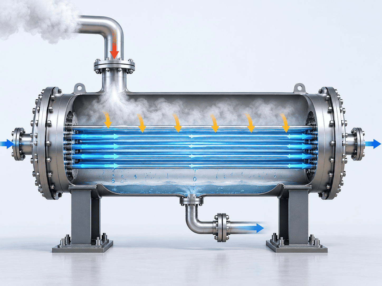
Shell and tube condenser cutaway showing steam condensing around the tube bundle and cooling water flowing through the tubes
Cooling-Water Sensitivity

Why Summer Cooling-Water Temperature Matters

A condenser should be evaluated against the utility conditions it must actually meet, not only a favorable annual average. The example below shows how a warmer cooling-water condition reduces the available temperature driving force.

Case A

Moderate Cooling-Water Condition

Water In 25°C
→
Water Out 35°C
Condensing Temperature 45°C
LMTD 14.43 K
Case B

Warmer Summer Cooling Water

Water In 30°C
→
Water Out 40°C
Condensing Temperature 45°C
LMTD 9.10 K

Same Duty, Less Temperature Driving Force

For this idealized isothermal example, the required thermal conductance is inversely proportional to the log mean temperature difference when the heat duty is fixed.

Case A Required UA 1.000×
→
Case B Required UA 1.585×
Illustrative Increase +58.5% UA

Only if the overall heat-transfer coefficient remains unchanged would this correspond to approximately 58.5% more heat-transfer area.

This is not a universal “5°C warmer water = 58.5% more area” rule. Real mixtures, changing heat-transfer coefficients, different flow arrangements and actual utility limits require project-specific evaluation. Include the maximum cooling-water inlet temperature, available flow and acceptable outlet condition in the quotation basis.
Solvent Recovery

Recovery Rate Is Not Condensate Purity

“High recovery” is incomplete unless the recovered component, collection boundary and outlet criteria are defined. Recovery, condensate composition and remaining vapor are different performance measures.

Illustrative Component Balance

Example Only
Target solvent entering the condenser 100 kg/h
Target solvent collected in condensate 95 kg/h
Water collected with the solvent 20 kg/h
Total collected condensate 115 kg/h
Target Solvent Recovery 95% 95 kg/h recovered from 100 kg/h entering.
Solvent in Condensate 82.6 wt% 95 kg/h solvent in 115 kg/h total condensate.
Buyer Takeaway

95% Recovery Does Not Mean 95% Purity

The recovered liquid can contain water or other condensable components even when most of the target solvent is captured. The outlet gas condition is a third, separate requirement.

Recovery Rate How much of the specified inlet component is collected.
Condensate Purity The composition of the collected liquid after co-condensation.
Residual Vapor / Outlet Concentration What remains in the gas stream leaving the condenser.
For VOC condenser applications, outlet concentration and outlet gas temperature are among the important performance indicators identified by the U.S. EPA. For project-specific solvent-recovery duties, define the intended downstream reuse or treatment requirement for the recovered liquid and review the application within the chemical industry or petrochemical industry context.
Vacuum Service

Vacuum Service, Non-Condensables and Drainage

A vacuum condenser operates as part of a system. Condensation, remaining gas removal and liquid discharge need to be reviewed together rather than treated as three unrelated connections.

Vacuum condenser system with receiver, condensate drain and downstream vacuum pump for industrial service

Use Absolute Pressure

Specify the actual operating pressure at the relevant inlet and outlet locations. For mixtures, total pressure alone does not define the condensation condition.

Protect the Pressure-Drop Budget

Include condenser losses and connecting-line losses in the vacuum-system review. A pressure loss that appears small in pressurized service can materially affect low-pressure operation.

Define the Remaining Gas Load

State the expected non-condensable flow and any residual process vapor at the condenser outlet instead of assuming downstream vacuum equipment handles only air.

Design the Liquid Route Separately

Confirm receiver pressure, elevation, level control and the liquid-discharge arrangement so condensate does not accumulate where it interferes with vapor flow or system stability.

System Boundary Matters

A conceptual arrangement may include the condenser, receiver, vacuum equipment, off-gas treatment, piping and controls. The actual supply boundary should be stated explicitly in the quotation.

Explore Process Skid Systems
Configuration & Maintenance

Choose a Condenser Configuration You Can Maintain

The best construction is not simply the one with the lowest first cost. Start with where deposits are likely to form, how the unit will be cleaned and whether the plant has enough space to remove the parts that are meant to be removable.

Selection Logic

Start With Maintenance, Not Just Geometry

Condenser configuration should be evaluated together with fouling tendency, cleaning method, differential expansion and the available maintenance envelope.

Which side is most likely to foul?
Does cleaning require mechanical access?
Can the bundle actually be withdrawn on site?
How will thermal expansion be accommodated?

Fixed Tubesheet

Simple Construction
Maintenance & Expansion

Straight-tube internal access can be provided, but the tube bundle is normally not removable. Shell-side mechanical access is therefore limited and differential expansion must be checked.

Procurement Question

Is the shell side clean enough, or is there a practical cleaning method that does not require bundle removal?

U-Tube

Expansion Friendly
Maintenance & Expansion

A removable bundle can improve shell-side access and accommodate differential expansion. Straight-through mechanical rodding cannot pass around the U-bend.

Procurement Question

Is the chosen tube-side cleaning and inspection method suitable for the return bends and the expected deposits?

Floating Head

Maximum Access
Maintenance & Expansion

A removable straight-tube bundle can support access on both sides and accommodate differential expansion, depending on the detailed head arrangement.

Procurement Question

Do the cleaning and inspection benefits justify the additional joints, space requirement and mechanical complexity?

Removable does not automatically mean accessible. Check bundle-withdrawal clearance, channel-cover space, lifting route and nearby piping before approving the layout.
Material Selection

Materials Must Work on Both Sides

The process vapor is only one part of the materials decision. Cooling-water chemistry, local temperatures, cleaning chemicals and shutdown conditions can be just as important as the process-side fluid.

Stainless steel condenser tubesheet and tube bundle detail during fabrication and assembly

Process-Side Review

Vapor / Condensate

Provide vapor and condensate composition, concentration changes, impurities, operating temperature range and known deposit risks. Identify the cleaning chemicals the plant expects to use.

Cooling-Side Review

Utility Water

Provide the cooling-water source, chloride level, treatment chemicals, suspended solids and relevant temperature range. A stainless grade selected for the process side is not automatically suitable for the cooling-water side.

Specify Materials by Component

Different parts of the condenser can face different fluids, temperatures and fabrication constraints.

Tubes Exact grade, outside diameter, wall thickness and applicable product specification.
Tubesheets Solid alloy or specified clad/composite arrangement where appropriate.
Shells & Channels Material, mechanical design conditions and corrosion allowance where required.
Tube-to-Tubesheet Joints Joint arrangement and verification requirements matched to service and fabrication method.
Gaskets & Seals Compatibility with process fluids, cooling utility, temperature and cleaning chemicals.
Carbon steel, 304/316L stainless steel, selected duplex grades, titanium and nickel alloys are project-specific options, not a universal corrosion ranking. 316L should not be treated as a blanket solution for every chloride-containing service.
Quotation Comparison

Compare Condenser Quotations on the Same Design Basis

A lower price or a smaller heat-transfer area means little if the suppliers used different vapor loads, cooling-water temperatures, fouling assumptions or outlet targets.

Procurement Rule Normalize the design basis first. Compare price and surface area second.
Illustrative quotation comparison — not actual supplier data. The values below are used only to show how different design assumptions can change the apparent proposal.
Comparison Item
Quote A
Quote B
What to Resolve Before Award
Vapor Flow
5,000 kg/h
5,000 kg/h
Confirm identical composition, pressure and inlet state, not only the same mass flow.
Cooling-Water Inlet
28°C
32°C
Recalculate both proposals against the utility condition the plant actually has to meet.
Vapor-Side ΔP Limit
8 kPa
3 kPa
Identify which pressure-drop limit the process can tolerate, especially under vacuum.
Outlet Target
Defined liquid condition
“High-efficiency condensation”
Replace broad wording with measurable outlet phases, temperatures or component criteria.
Non-Condensables
Quantified in basis
Not stated
Use the same gas load and outlet assumptions in both thermal calculations.
Fouling / Margin
Defined basis
Not stated
Align fouling resistance, design allowance and the method used to apply any margin.
Supply Scope
Condenser body only
Condenser + receiver
Separate the thermal comparison from differences in equipment and documentation scope.

A Smaller Condenser Is Not Automatically a Better Design

A smaller quoted area may come from a more favorable cooling-water temperature, a higher assumed heat-transfer coefficient, a lower fouling allowance, a larger permitted pressure drop or omitted non-condensable load.

Cooling-water design temperature
Assumed heat-transfer coefficient
Fouling resistance
Allowable pressure drop
Peak vapor load
Non-condensable gas basis
Buyer Takeaway Compare Thermal Performance Under One Agreed Design Basis

A larger area is not automatically better either. Compare the complete duty, pressure drop, materials, maintainability and supply scope before deciding which proposal is technically stronger.

Custom Heat Exchangers
Acceptance Basis

Define Performance, Inspection and Acceptance Before Ordering

Turn the approved design basis into a clear acceptance plan. Thermal performance, mechanical verification and certification are related, but they are not the same deliverable and should not be treated as interchangeable proof.

Thermal Performance Basis

Process Acceptance

Agree which operating case will be used to judge the condenser and how any off-design test condition will be corrected or interpreted.

Operating Case Composition, vapor flow, pressure, inlet state and utility condition.
Required Result Duty, outlet phase, temperature, recovery or concentration target as applicable.
Hydraulic Limit Allowable pressure drop on both process and cooling sides.
Evaluation Method Instrumentation, stabilization period, tolerances and agreed correction method.

Mechanical Inspection & Documentation

Fabrication Evidence

Specify the material records, welding documentation, dimensional checks, applicable non-destructive examinations, pressure or leakage testing and release documents required for the project.

Material Traceability Required material certificates and component identification.
Welding Records Approved procedures and required production records.
NDT Scope Methods and extent selected for the material, weld and governing requirements.
Pressure / Leak Test Method, test boundary and acceptance requirement defined before fabrication release.

Codes, Marking and Certification

Project Requirements

State the applicable code, edition, any TEMA requirements, third-party involvement, marking and documentation scope in the purchase specification. A reference to a standard is not itself proof of certification.

Design Code Applicable code and edition for the pressure boundary and project.
TEMA Requirements Mechanical exchanger requirements where specified by the project.
Third-Party Inspection Witness, hold or review points defined in the inspection plan.
Certification / Marking Required certificate or mark confirmed against the authorized manufacturing scope.
A hydrostatic test does not measure condensing duty or prove a solvent-recovery target. A thermal calculation does not replace the required mechanical verification. Keep both acceptance paths explicit.

Certification reference: ASME Boiler and Pressure Vessel Certification.

Quality inspection of an industrial stainless steel condenser during factory fabrication and dimensional verification
Troubleshooting & Replacement

Check the Operating Data Before Replacing the Condenser

Poor performance can come from changed process conditions, warmer utilities, fouling, instrumentation problems or a genuine equipment limitation. Compare current readings with the original design basis before concluding that more area is required.

Diagnostic Rule Start with measured operating data. Do not diagnose from one symptom alone.
Higher Vapor Outlet Temperature
Record First

Actual vapor load, operating pressure, coolant inlet temperature, coolant flow and outlet conditions.

Review Direction

Changed duty, warmer utilities, insufficient coolant flow, fouling or reduced heat-transfer performance.

Higher Cooling-Side Pressure Drop
Record First

Cooling flow, inlet/outlet pressures, recent cleaning history and any utility-system changes.

Review Direction

Fouling, blockage, higher-than-design flow, valve position or instrument accuracy.

Larger Cooling-Water Temperature Rise
Record First

Measured cooling-water flow, inlet and outlet temperatures, and the actual vapor load.

Review Direction

Reduced utility flow, increased heat load or a change in operating duty relative to the original design case.

Higher Process-Side Pressure Drop
Record First

Vapor flow, composition, pressure readings, cooling condition and any known deposit history.

Review Direction

Incomplete condensation, changed loading, fouling, flow maldistribution or an altered downstream system condition.

Replacement Enquiry

Send More Than the Old Drawing

A dimensional match does not automatically provide a thermal match. If the process or utility conditions have changed, the existing envelope should be checked against the current duty.

Existing datasheet and general arrangement drawing
Nozzle orientation, support dimensions and available maintenance space
Material records and original design conditions if available
Recent operating temperatures, pressures and flow readings
Description of fouling, corrosion, leakage or performance symptoms
Any permanent process or cooling-utility changes
Confirm both physical interchangeability and current thermal performance before approving a replacement design.
Maintenance & Troubleshooting
FAQs & Enquiry

Condenser FAQs

Use these questions to clarify the enquiry before quotation. A complete process datasheet is helpful, but the discussion can start with the application, known fluid, estimated load and available cooling utility.

Can You Quote From an Existing Condenser Drawing?

Yes. Send the drawing and any available process datasheet. State whether the request is for manufacture to an approved design, a dimensional replacement or a new thermal assessment. If service conditions have changed, the duty should be reviewed before copying the original unit.

Can a Condenser Include Liquid Subcooling?

Yes, when subcooling is part of the specified duty. State the required liquid outlet temperature separately from the condensation target so both the latent and sensible heat loads are included in the thermal review.

Is the Receiver or Vacuum Pump Included?

Not automatically. The quotation should identify whether the supply includes only the condenser or also the receiver, vacuum equipment, piping, instruments, controls or skid structure. Package boundaries should be agreed explicitly.

Can the Condenser Use Chilled Water or Glycol?

These utilities can be evaluated when their composition, inlet temperature, available flow and operating range are supplied. A cooling-water example should not be reused unchanged for glycol or another coolant.

What if the Vapor Composition Is Not Fully Known?

Send the process description, known components and any available analysis. The enquiry can begin before every field is complete, but unresolved composition or non-condensable load must be identified because they can affect thermal sizing and performance commitments.

Can We Specify ASME or Other Project Requirements?

Yes. State the required design code, edition, marking, inspection involvement and document scope in the enquiry. The quotation should confirm the applicable manufacturing and certification arrangement rather than relying on a general website statement.

What Is Needed for an Initial Enquiry?

Start with the application, known vapor or fluid, estimated flow or existing model, operating pressure and temperature, available cooling utility and the required outlet result. Unknown fields can be marked “To be confirmed.”

Scroll to Top
DRAWING & FILE REVIEW

Send Your Drawings

Upload your drawings, datasheets or existing specifications. Our engineering team will review the files and respond with technical feedback.

Engineering Review

Drawings, specifications and process requirements

Confidential File Handling

Project files are used only for technical review and quotation

Faster Technical Feedback

Clearer inputs help us respond more accurately and efficiently

DRAWING & FILE REVIEW

Send Your Drawings

Upload your drawings, datasheets or specifications. Our engineering team will review your files and provide technical feedback.

Contact Form Demo (#3)
Project Protected NDA available
12h Response
ASME / PED
AFTER SUBMISSION
01 Review
→
02 Confirm
→
03 Quote
TECHNICAL QUOTATION

Get a
Technical Quote

Tell us what you need. Our engineering team will review your requirements and respond within 12 hours.

Engineered for Your Application

From concept to certified manufacturing

Global Compliance

ASME, PED and other international standards

Expert Support

Direct access to our engineering team

TECHNICAL QUOTATION

Get a Technical Quote

Tell us what you need. Our engineering team will review your requirements and respond within 12 hours.

Contact Form Demo
Project Protected NDA available
12h Response
ASME / PED
AFTER SUBMISSION
01 Review
→
02 Confirm
→
03 Quote