ChannelVessel Intelligent Equipment Co., Ltd. Contact Us
PROCESS-ENGINEERED CHEMICAL REACTORS

Chemical Reactors Engineered Around Your Process

Custom chemical reactors designed around reaction chemistry, mixing duty, heat transfer, materials, pressure and control requirements — not vessel volume alone.
50–20,000 L Custom Capacity Range
Vacuum to Pressure Process-Specific Design
SS304 / SS316L Corrosion-Resistant Options
Useful inputs Capacity Media Temperature Pressure Mixing objective
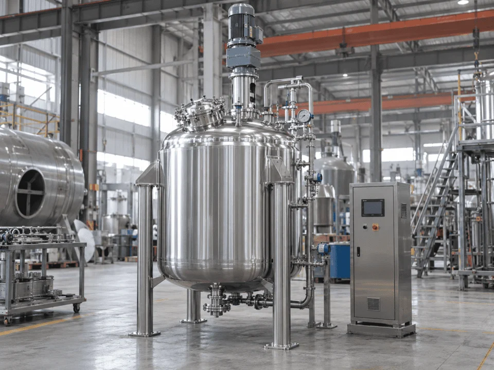
Custom industrial chemical reactor with agitation and jacketed vessel construction
PROCESS BEFORE VOLUME

A Chemical Reactor Is Not Selected by Volume Alone

Two 5,000 L reactors can require completely different vessel geometry, agitation, heat-transfer area, materials and pressure design. The process conditions determine the equipment.

Reaction Behavior Design Driver

The chemistry determines how the vessel must behave.

Reaction rate, exothermic or endothermic behavior, sensitivity to temperature and feed strategy can change the required mixing intensity, heat-removal capacity and control architecture.

We check Heat release or heat demand
We check Reaction rate and feed sequence
We check Temperature sensitivity
ENGINEERING CONSEQUENCE

May change jacket area, coil requirement, agitator configuration, feed location, instrumentation and control strategy.

Same volume 5,000 L
≠
Same reactor Not necessarily

Capacity defines how much product the vessel holds. Process conditions define how the reactor must be engineered.

PROCESS → ENGINEERING DIRECTION

Build the Reactor Around the Process

Select a few basic process conditions to see which engineering areas deserve the most attention. This is not a final reactor calculation — it shows how process inputs change the design direction.

Reaction Behavior How the reaction handles heat
Process Phase What must be contacted or suspended
Viscosity How difficult the batch is to move
Pressure Condition Mechanical design basis
ENGINEERING FOCUS

Heat removal and controlled mixing should lead the design.

Live Process View
Heat Transfer Prioritize cooling duty and available heat-transfer area.
Mixing Select impeller geometry for liquid circulation and temperature uniformity.
Mechanical Design Atmospheric service keeps the mechanical basis relatively simple.
Additional Attention Check feed rate, hot spots and reaction temperature response.
THERMAL ENGINEERING

Heat Removal Comes Before Heating Method

Jacket, half-pipe or coil is not the first decision. The first question is how much heat must be added or removed, how quickly, and with which utility.

Reaction Heat Generation or Demand

Understand whether the process releases, absorbs or is sensitive to heat.

→
Duty Required Thermal Load

Define heat-up, cool-down and reaction-control requirements.

→
Area Heat-Transfer Surface

Determine how much effective area is needed for the process duty.

→
Utility Available Plant Utility

Steam, hot water, thermal oil, cooling water or chilled media.

→
Configuration Jacket / Half-Pipe / Coil

Select the heat-transfer geometry after the thermal basis is clear.

Jacketed or half-pipe chemical reactor under fabrication in factory

A real jacketed or half-pipe reactor under fabrication, showing welds and heat-transfer construction clearly.

Conventional Jacket

A practical choice when the required duty can be met with vessel-wall heat transfer and standard utility conditions.

Heating Cooling General Process Duty
Half-Pipe Jacket

Useful where stronger utility-side flow, higher jacket-side pressure capability or more controlled circulation is required.

Steam Thermal Oil Higher Utility Demand
Internal Coil

Adds heat-transfer area inside the vessel when the external surface alone cannot provide enough thermal duty.

Added Area Fast Duty Process-Specific
External Loop

Can be considered when heat-transfer duty, fouling control or process circulation benefits from an external exchanger loop.

External Exchanger Circulation Custom System
Why this matters for exothermic reactions

If heat generation exceeds the system's ability to remove heat, reactor temperature can rise rapidly. Cooling capacity, reaction conditions and control strategy therefore need to be considered together.

HSE Reaction Hazard Guidance ↗
MIXING ENGINEERING

Mixing Is a Process Requirement, Not an Impeller Choice

The impeller should be selected after the mixing objective is clear. Blending liquids, suspending solids, dispersing gas and moving a high-viscosity batch all require different flow patterns, torque and geometry.

WHAT MUST THE MIXER DO?

Select the main duty to see which design variables matter most.

Stainless steel chemical reactor interior with agitator shaft, dual impellers and baffles

Reactor geometry, baffle arrangement, shaft position and impeller configuration are engineered together around the required mixing duty.

LIQUID–LIQUID BLENDING

Prioritize circulation and batch uniformity.

For miscible liquids, the design should create effective top-to-bottom and radial circulation without adding unnecessary shear or motor power.

Primary concern Bulk flow pattern
Design variable Impeller diameter & position
Check during scale-up Mixing time and power input
ENGINEERING DIRECTION

A circulation-focused impeller with suitable diameter, clearance and speed is typically more important than maximizing RPM.

Impeller Geometry follows duty
+
Motor & Gearbox Torque follows viscosity
+
Vessel Geometry Flow follows dimensions
=
Reactor Mixing System Engineered as one system
MATERIAL COMPATIBILITY

Material Selection Starts With the Chemical Environment

A chemical name alone is not enough to select reactor material. Concentration, temperature, contaminants, cleaning media and exposure conditions can change the corrosion behavior of the same alloy.

Medium What chemicals contact the vessel?
→
Concentration How strong is the process solution?
→
Temperature At what temperature does exposure occur?
→
Contaminants Are chlorides, solids or trace species present?
→
Cleaning What cleaning chemicals contact the surfaces?
ENGINEERING VIEW

Change one process condition and the material decision may change with it.

Interactive Material Logic
CONCENTRATION EFFECT

The same chemical can behave differently at a different concentration.

Corrosion rate, passivation behavior and localized attack can all change as concentration changes. Material selection should use the actual process composition rather than a generic chemical name.

Use operating and maximum concentration, not only nominal values.

Consider concentration changes during evaporation or reaction.

Check both process and cleaning exposure.

MATERIAL DECISION

Do not move directly from “chemical name” to “316L”. First confirm the real exposure conditions and corrosion mechanism.

SS304 General industrial service where compatible
SS316L Improved corrosion resistance for many chemical duties
Hastelloy For more aggressive corrosive environments when required
Titanium Specialized option for selected highly corrosive media
Important

Final material suitability should be confirmed against the actual process chemistry and design conditions.

Wetted Parts Matter Too

Nozzles, dip pipes, thermowells, agitator shafts, impellers and internal coils should follow the same compatibility logic as the vessel shell.

Seals & Gaskets Are Part of the Material System

Mechanical seals, gaskets and elastomers can become the weak point even when the vessel alloy itself is suitable.

Cleaning Can Be More Aggressive Than the Process

Caustic, acidic or oxidizing cleaning chemicals may require separate compatibility checks from the normal batch chemistry.

COMMON FAILURE MODES

Where Reactor Designs Commonly Fail

Many reactor problems are not caused by one bad component. They come from process conditions, geometry, mixing, heat transfer, materials and scale-up decisions that do not work together as a system.
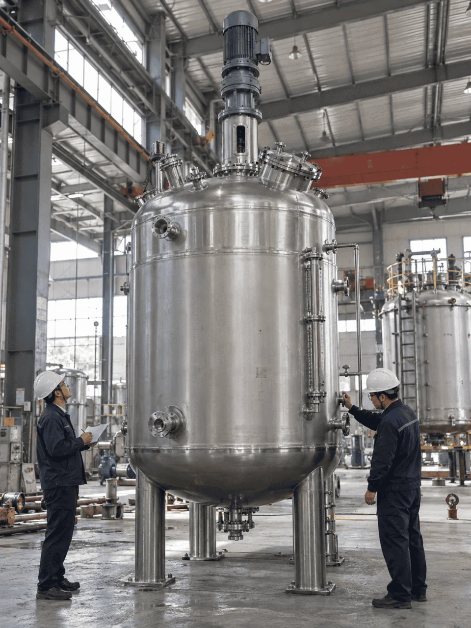
CLICK A HOTSPOT See what usually goes wrong
Chemical reactor inspection scene in factory
THERMAL CONTROL Failure Mode

Hot spots can appear when heat is generated faster than it is removed.

The reactor may have enough nominal jacket area on paper, but poor circulation, insufficient utility flow or a fast exothermic reaction can still create local temperature rise.

Typical cause Insufficient heat-transfer duty or poor wall-side circulation
What it can affect Temperature control, reaction rate and product consistency
Engineering response Recheck duty, mixing, heat-transfer area and utility conditions together
DESIGN TAKEAWAY

Do not evaluate cooling capacity separately from mixing and reaction heat generation.

Reactor reliability improves when thermal, mixing, mechanical and material decisions are checked against the same process basis.

Heat Mixing Materials Mechanical Design Scale-Up
SCALE-UP ENGINEERING

From Lab Reactor to Production Reactor

Scaling a reactor is not simply a matter of increasing every dimension by the same ratio. Mixing, heat transfer, circulation and mechanical behavior change as vessel size increases.

Chemical reactor scale-up from laboratory to pilot and production scale

Illustrative scale-up path only. Final production design depends on the actual process, chemistry, utility and operating criteria.

HEAT TRANSFER

Heat-transfer area does not grow as quickly as reactor volume.

As a reactor becomes larger, the amount of reacting material increases faster than the available vessel surface area. A production reactor may therefore need a different jacket arrangement, added coil area or a different cooling strategy.

Recalculate heat-up and cool-down duty.

Check reaction heat against available cooling capacity.

Confirm utility flow and temperature at production scale.

What changes during scale-up?
Lab Fast response
Pilot Intermediate behavior
Production More thermal inertia
ENGINEERING TAKEAWAY

Keep the process objective constant, then redesign the equipment around the new scale.

Same recipe? Possibly
≠
Same geometry? Not necessarily
≠
Same RPM? Usually not
≠
Same process objective? Yes — that is what should be preserved
REACTOR CONFIGURATIONS

Choose the Configuration Around the Process Duty

Reactor configuration should follow the process requirements already defined: heat transfer, mixing, pressure, vacuum, materials and control. The vessel type is the result of those decisions, not the starting point.
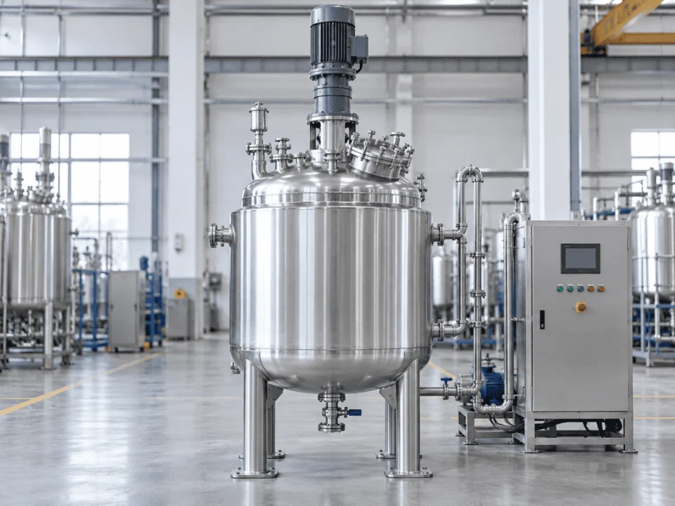
Jacketed chemical reactor in industrial factory

Best image direction: a vertical stainless-steel reactor with visible jacket construction, top-entry agitator and process nozzles.

THERMAL CONTROL CONFIGURATION

Jacketed Reactor

A jacketed reactor is suitable when heating, cooling or temperature control is a primary part of the process design. Jacket geometry should be selected from the required duty and available plant utility.

Best suited for Batch heating, cooling and controlled reaction temperature
Key engineering focus Heat-transfer area, utility flow and wall-side circulation
Common options Conventional jacket, half-pipe jacket, insulation and temperature control
Heating Cooling Temperature Control
ENGINEERING INPUTS

What We Need Before Engineering Your Reactor

The more complete the process data, the faster the reactor configuration can be defined. Start with the information you already have — we can help identify what is still missing.

RFQ readiness 20%

You do not need every value before contacting us. Even partial process data is enough to start the engineering discussion.

PROCESS BASIS

Start with what the reactor must process.

Capacity and chemistry define the first layer of the reactor design. Working volume alone is not enough — the media, process mode and phase behavior matter too.

ENGINEERING HANDOFF

Send the data you have. We will identify what still needs to be defined.

Process conditions can be sent as notes, specifications, P&ID, datasheets or drawings.

Unknown values can be reviewed during the engineering discussion instead of guessed.

More complete inputs reduce back-and-forth and help avoid wrong assumptions in the initial configuration.

Most useful starting inputs
Volume Media Temperature Pressure Viscosity Mixing duty

If the process is still at laboratory or pilot stage, send the current recipe, batch size, temperature profile and mixing conditions. These are often enough to start a scale-up discussion.

FABRICATION & VERIFICATION

Build the Reactor So the Final Documentation Matches the Equipment

Fabrication quality is not only what the finished reactor looks like. Material traceability, welding records, inspection, pressure testing and final documentation should all connect back to the approved design basis.
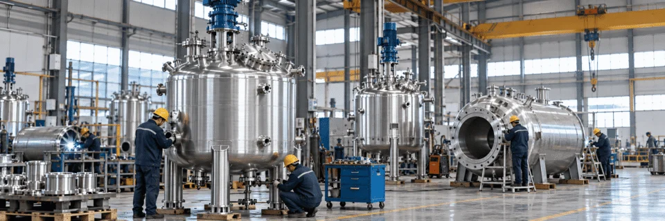
Chemical reactor fabrication and inspection in industrial factory

Best image direction: a real stainless-steel reactor under fabrication or final inspection inside a Chinese factory, with welding, dimensional inspection or pressure-test preparation visible.

MATERIAL CONTROL

Confirm the material before fabrication starts.

Plates, heads, nozzles and other pressure-retaining parts should be identified against the required material specification before they enter fabrication.

Expected evidence
Material certificates Heat / batch traceability Incoming inspection
WELDING CONTROL

Use qualified procedures and qualified welders.

Joint preparation, welding sequence, filler material and welder qualification should match the approved fabrication requirements and applicable code basis.

Expected evidence
WPS / PQR Welder qualification Weld map
NDT & INSPECTION

Verify critical welds before the vessel is closed out.

Visual inspection and required nondestructive examination should be completed at the specified stages so defects are found before final assembly or testing.

Expected evidence
VT records PT / RT / UT as required NDT reports
PRESSURE TEST

Test the completed pressure boundary against the design basis.

Hydrostatic or other approved pressure testing is performed after fabrication and inspection are complete, according to the required code and project procedure.

Expected evidence
Test procedure Pressure-test record Gauge calibration
FINAL VERIFICATION

Check dimensions, finish, nozzles and documentation before shipment.

Final inspection should confirm the reactor matches the approved drawing, required surface condition, nozzle orientation and ordered accessories.

Expected evidence
Dimensional report Final drawings Inspection release
DELIVERY DOCUMENT PACKAGE

What the buyer should be able to receive with the reactor

Project-specific package
Material Records

Material certificates and traceability records for applicable pressure-retaining parts.

Welding Records

Applicable WPS, PQR, welder qualification and weld identification records.

NDT Reports

Inspection reports for the nondestructive examination required by the project.

Pressure-Test Record

Test pressure, holding condition, result and instrument information as applicable.

Dimensional Inspection

Key dimensions, nozzle orientation and final equipment configuration checked against drawing.

Final Drawings

Approved or as-built drawings reflecting the manufactured reactor configuration.

CHEMICAL APPLICATIONS

Chemical Reactors for Different Process Environments

Different industries place different demands on mixing, heat transfer, corrosion resistance, pressure control and documentation. The reactor configuration should follow the process environment rather than a fixed product template.

Chemical industry reactor equipment
CHEMICAL

Chemical Processing

For corrosive, heated, mixed or pressurized chemical processes where material selection, sealing and welding quality directly affect equipment performance.

Corrosion Mixing Thermal Control
View Chemical Industry →
Petrochemical process equipment
PETROCHEMICAL

Petrochemical Processing

For higher-temperature, higher-pressure and hydrocarbon process conditions where mechanical design, inspection records and project documentation matter.

Pressure Thermal Duty Containment
View Petrochemical Industry →
Oil and gas process equipment
OIL & GAS

Oil & Gas Processing

For pressure holding, gas-liquid service, separation and process duties where equipment reliability, nozzle design and traceability are important.

Pressure Gas-Liquid Traceability
View Oil & Gas Industry →
Pharmaceutical stainless steel process equipment
PHARMACEUTICAL

Pharmaceutical Processing

For cleanable stainless-steel process equipment where internal finish, dead zones, material compatibility and cleaning method cannot be ignored.

Cleanability 316L Process Control
View Pharmaceutical Industry →
Water treatment process equipment
WATER TREATMENT

Water Treatment

For filtration, chemical dosing, separation and pressure-holding applications where vessel internals, corrosion resistance and process integration matter.

Filtration Corrosion Pressure
View Water Treatment →
New energy process equipment manufacturing
NEW ENERGY

New Energy Materials

For battery materials, solvent handling, reaction and thermal processes where corrosion resistance, sealing, cleanliness and solids handling may affect output.

Slurry Solvents Cleanliness
View New Energy Industry →
ENGINEERING FAQ

Questions to Resolve Before Final Reactor Design

Final reactor configuration depends on process data, not a standard model number. These are the questions that most often affect equipment selection, quotation accuracy and engineering time.

No. Working volume is only one input. Reaction behavior, heat duty, viscosity, phase system, pressure, vacuum, material compatibility and mixing objective can all change the final vessel geometry and equipment configuration.

The main mixing objective should be defined first: blending, solids suspension, gas dispersion, heat-transfer support, high-viscosity circulation or wall-buildup control. Viscosity, solids loading, gas rate, liquid level and batch behavior are also important.

A half-pipe jacket may be considered when utility-side flow, jacket-side pressure capability or higher thermal duty requires a different heat-transfer arrangement. The decision should follow the actual thermal load and available utility conditions.

It depends on the complete exposure environment. Chemical concentration, temperature, contaminants, cleaning media and contact time should be reviewed before confirming material suitability. The same chemical can behave differently under different process conditions.

Not by geometric scaling alone. Mixing time, impeller tip speed, power per volume, heat-transfer area, circulation path and thermal response all change with scale. The process objective should be preserved while the equipment is re-engineered around production conditions.

Reaction heat, addition rate, operating temperature, maximum allowable temperature, required cooling response, batch volume and available utility conditions are especially important. Mixing and heat removal should be reviewed together.

Yes, when those conditions are included in the design basis. Vacuum and pressure introduce different mechanical checks, so operating pressure, design pressure and the required vacuum condition should all be specified before final design.

Depending on the project scope, documentation can include material certificates, welding records, NDT reports, pressure-test records, dimensional inspection, final drawings and other agreed quality documents.

Scroll to Top
DRAWING & FILE REVIEW

Send Your Drawings

Upload your drawings, datasheets or existing specifications. Our engineering team will review the files and respond with technical feedback.

Engineering Review

Drawings, specifications and process requirements

Confidential File Handling

Project files are used only for technical review and quotation

Faster Technical Feedback

Clearer inputs help us respond more accurately and efficiently

DRAWING & FILE REVIEW

Send Your Drawings

Upload your drawings, datasheets or specifications. Our engineering team will review your files and provide technical feedback.

Contact Form Demo (#3)
Project Protected NDA available
12h Response
ASME / PED
AFTER SUBMISSION
01 Review
→
02 Confirm
→
03 Quote
TECHNICAL QUOTATION

Get a
Technical Quote

Tell us what you need. Our engineering team will review your requirements and respond within 12 hours.

Engineered for Your Application

From concept to certified manufacturing

Global Compliance

ASME, PED and other international standards

Expert Support

Direct access to our engineering team

TECHNICAL QUOTATION

Get a Technical Quote

Tell us what you need. Our engineering team will review your requirements and respond within 12 hours.

Contact Form Demo
Project Protected NDA available
12h Response
ASME / PED
AFTER SUBMISSION
01 Review
→
02 Confirm
→
03 Quote