
ChannelVessel Intelligent Equipment Co., Ltd. Contact Us
PRESSURE VESSEL ENGINEERING GUIDE

Vessel Design Basics

A practical introduction to the engineering decisions behind pressure vessel design — from pressure, temperature and materials to geometry, openings, supports and fabrication requirements.

Pressure vessel design is not based on pressure alone. The final configuration develops from a combination of process conditions, mechanical loads, material properties, vessel geometry, applicable design rules and fabrication requirements.

From process conditions to fabrication-ready vessel design.
Pressure vessel engineering design and fabrication review
DESIGN BASIS Pressure · Temperature · Material · Loads
DESIGN FOUNDATION

A Pressure Vessel Is Defined by More Than Pressure and Volume

Two vessels with the same capacity and operating pressure can require very different mechanical designs. The final configuration develops from the complete service conditions, vessel geometry, material behavior and external loads acting on the equipment.

PRESSURE & TEMPERATURE

Define the mechanical design conditions.

Design pressure and design temperature establish the basic conditions the pressure boundary must withstand and influence material allowable values and required thickness.

PROCESS MEDIUM

Determines service compatibility.

The contained fluid or gas can affect material selection, corrosion allowance, cleanliness, sealing and other service-specific design decisions.

VESSEL GEOMETRY

Changes how the vessel behaves.

Diameter, length, orientation and head geometry influence pressure stresses, stability, supports, fabrication and the overall equipment arrangement.

EXTERNAL LOADS

Add forces beyond internal pressure.

Supports, piping, attached equipment, operating weight, wind and seismic conditions can introduce additional structural and local design requirements.

Pressure & Temperature + Medium + Geometry + External Loads = Mechanical Design Basis

For this reason, vessel design begins by defining the complete operating and design conditions rather than selecting a shell thickness from pressure alone.

CORE DESIGN INPUTS

The Core Inputs Behind Vessel Design

A reliable design starts with reliable project data. Some parameters directly influence pressure-retaining calculations, while others determine materials, geometry, supports, fabrication details or required design checks.

Design starts with the complete service condition.

Pressure, temperature, medium, geometry and site requirements should be reviewed together rather than treated as isolated inputs.

PRESSURE

Design Pressure

Establishes the pressure condition used for mechanical design and should reflect the defined design basis rather than simply repeating normal operating pressure.

TEMPERATURE

Design Temperature

Material strength and allowable design values vary with temperature, which can directly affect suitability and required pressure-retaining thickness.

SERVICE

Process Medium

The contained fluid or gas can influence corrosion resistance, material compatibility, contamination requirements, lining and sealing decisions.

CAPACITY

Required Volume

Working volume and total vessel volume influence vessel diameter, straight-side length, head space and overall geometry.

MATERIAL

Material

Material selection affects corrosion resistance, allowable stress, welding, surface requirements, fabrication and service life.

CORROSION

Corrosion Allowance

Where material loss is expected during service, an appropriate corrosion allowance may need to be included in the mechanical design.

CYCLING

Operating Cycles

Frequent pressure or temperature changes can introduce additional design considerations beyond a simple steady-state operating condition.

VACUUM

Vacuum Conditions

A vessel exposed to vacuum or external pressure requires a stability check that is fundamentally different from an internal-pressure strength calculation.

CONNECTIONS

Nozzles & Connections

Connection sizes, locations, loads and functions should be established early because openings affect both vessel layout and local strength.

INSTALLATION

Installation Conditions

Indoor or outdoor installation, support arrangement, wind, seismic requirements, transportation limits and site constraints can influence the final design.

DESIGN CONDITIONS

Pressure, Temperature & Load Cases Must Be Considered Together

A pressure vessel rarely experiences one pressure acting on an otherwise unloaded shell. Different combinations of pressure, temperature, weight and external forces can govern during operation, startup, shutdown, cleaning, testing or other defined conditions.

VESSEL Design Basis Evaluate the complete load condition
P
PRESSURE LOAD

Internal Pressure

Pressure acting outward on the vessel shell, heads and other pressure-retaining components.

V
STABILITY LOAD

External Pressure / Vacuum

Pressure acting inward can create instability and buckling even when the pressure differential appears relatively small.

W
WEIGHT LOAD

Operating Weight

The vessel may need to support its own weight together with liquid, internals, insulation and attached equipment.

H
LIQUID HEAD

Hydrostatic Head

For taller vessels or high-density liquids, static liquid head can increase pressure toward the lower part of the vessel.

E
SITE LOAD

Wind & Seismic Loads

Outdoor vessels and equipment installed in seismic regions may require structural checks for site-specific environmental loads.

N
LOCAL LOAD

Piping & Equipment Loads

Nozzles can receive forces and moments from connected piping, valves, platforms, agitators or other attached equipment.

T
SEPARATE LOAD CASE

Test Conditions

Hydrostatic or other specified test conditions create a separate mechanical load case that should be considered during engineering rather than assumed to be identical to normal operation.

KEY ENGINEERING POINT The governing design case may not be the normal operating condition.
Operation + Startup / Shutdown + Testing + Abnormal Conditions
VESSEL GEOMETRY

Shell, Heads & Vessel Geometry

Pressure vessel geometry affects more than appearance or available volume. Diameter, unsupported length, head type, orientation and transitions can influence required thickness, stability, fabrication and overall equipment cost.

CYLINDRICAL SHELL

The primary pressure-retaining body

Shell diameter, length, thickness and weld arrangement are fundamental mechanical inputs for many process vessels.

ELLIPSOIDAL HEADS

Balanced geometry for pressure service

Commonly used where an efficient pressure-retaining geometry and practical fabrication are required.

TORISPHERICAL HEADS

Compact and widely used

Frequently selected for process vessels where manufacturing, space and project requirements make them suitable.

HEMISPHERICAL HEADS

Favorable pressure stress distribution

They provide efficient pressure behavior, although greater depth and different fabrication considerations must be evaluated.

FLAT COMPONENTS

Require different structural treatment

Flat heads and covers can behave very differently from formed heads and may require substantially different thickness or reinforcement.

ORIENTATION

Vertical or horizontal arrangement

Orientation affects supports, nozzle arrangement, drainage, maintenance access, transportation and site layout.
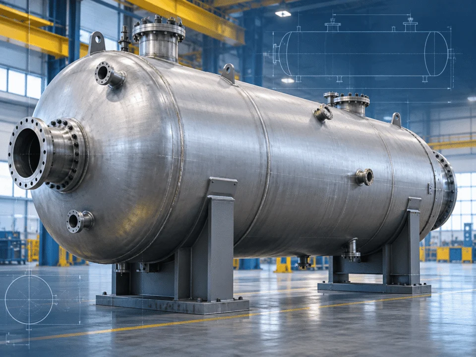
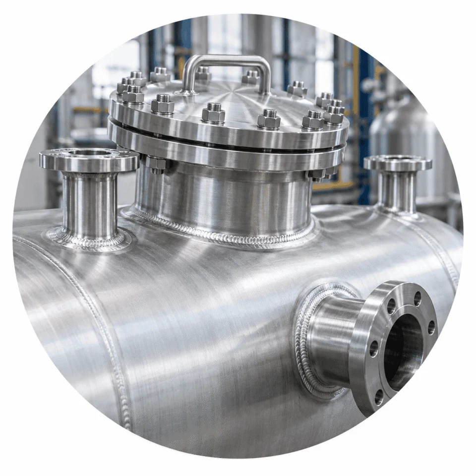
ENGINEERING PRINCIPLE A vessel should be proportioned as a complete mechanical system rather than treating capacity, diameter and wall thickness as independent selections.
Pressure vessel shell and head geometry
GEOMETRY AFFECTS
Thickness Stability Supports Fabrication
MATERIAL SELECTION BASICS

Material Selection Starts With the Service

Material selection is not simply a choice between carbon steel and stainless steel. The correct material depends on the process medium, design temperature, corrosion environment, cleanliness requirements, fabrication requirements and applicable project specifications.

GENERAL INDUSTRIAL SERVICE

Carbon Steel

Often suitable for general industrial pressure service when corrosion conditions, process cleanliness and project requirements permit.

Cost efficiency General pressure service Coating may be required
CORROSION & CLEANLINESS

Stainless Steel 304

Commonly considered where improved corrosion resistance and cleaner product-contact surfaces are required.

Clean process surfaces Improved corrosion resistance Food / general process use
MORE DEMANDING SERVICE

Stainless Steel 316L

Frequently considered for services requiring greater resistance to certain corrosive environments or enhanced process cleanliness.

Higher corrosion resistance Clean service Process-specific selection
PROJECT-SPECIFIC

Special or Specified Materials

Other alloys or project-specified materials may be required where common carbon or stainless steels do not match the defined service conditions.

Special corrosion conditions Temperature limits End-user specification
WALL THICKNESS

Wall Thickness Is Not Just a Pressure Calculation

A calculated pressure thickness is only one input into the final specified vessel thickness. The nominal plate or shell thickness selected for fabrication may also need to account for corrosion, tolerances, forming, external-pressure stability, local loads and practical fabrication requirements.

BASE INPUT Pressure Requirement
+
Corrosion Allowance Material Tolerance Forming Effects External Pressure Local Loads Fabrication Practicality
=
ENGINEERING OUTPUT Selected Nominal Thickness
PRESSURE

Pressure Requirement

Internal pressure establishes a basic pressure-retaining thickness requirement for shells and heads under the defined design pressure and temperature.

CORROSION

Corrosion Allowance

Where material loss is expected during service, additional thickness may be required beyond the calculated pressure thickness.

TOLERANCE

Material Tolerance

The nominal material thickness selected for fabrication should account for applicable dimensional tolerances and the actual supplied product form.

FORMING

Forming Considerations

Head forming and other manufacturing operations can influence final geometry and local thickness, so fabrication effects should be considered during design.

STABILITY

External Pressure Stability

A shell that is adequate for internal pressure may still be unsuitable for vacuum or external pressure if buckling resistance is insufficient.

LOCAL EFFECTS

Local Loads

Openings, nozzles, supports, attachments and connected equipment can introduce local effects that require separate engineering evaluation.

FABRICATION

Fabrication Practicality

The final selected thickness should also be practical for forming, welding, handling, available plate sizes and the intended fabrication route.

KEY POINT Required thickness = more than pressure alone.

The mechanically selected nominal thickness is the result of the complete design basis, not a single isolated formula.

Pressure vessel nozzle and manway reinforcement detail
OPENING DESIGN Pressure boundary + reinforcement + external loads
NOZZLES & OPENINGS

Every Opening Changes the Pressure Boundary

Nozzles, manways, instrument connections and other openings interrupt the continuity of the shell or head. Their effect therefore has to be considered as part of the pressure-retaining design rather than treated as a simple fabrication detail.

OPENING SIZE

Larger openings remove more pressure-retaining material

As opening size increases, the surrounding shell or head may require additional reinforcement consideration to maintain the intended pressure boundary performance.

LOCATION

Position affects the local design condition

Openings located near heads, transitions, other nozzles or structural discontinuities may require additional engineering attention.

REINFORCEMENT

Material around the opening may need to be restored

Where required, reinforcement can be provided through available excess thickness, nozzle neck material, reinforcement pads or other permitted design approaches.

EXTERNAL LOADS

Piping can transfer forces into the vessel

Connected piping, valves, instruments or equipment can introduce forces and moments into the nozzle and surrounding vessel wall.

ACCESS & MAINTENANCE

Nozzle arrangement is also a practical layout decision

Connection locations should consider operation, internal access, inspection, drainage, cleaning, maintenance and future equipment servicing — not only pressure calculations.

DESIGN RELATIONSHIP
Opening → Local Strength → Reinforcement → Nozzle Loads → Final Nozzle Design

Nozzle design therefore combines pressure-boundary requirements with piping, process and equipment-layout requirements.

SUPPORTS & EXTERNAL LOADS

The Vessel Must Support More Than Pressure

A completed pressure vessel must safely transfer its own weight and the loads from process contents, internals, piping, platforms, agitators and environmental conditions into the support system and ultimately into the foundation.

VERTICAL VESSELS

Skirt Supports

Common for vertical vessels where the equipment load needs to be transferred continuously into the foundation through a cylindrical or conical support structure.

SMALLER VERTICAL VESSELS

Leg Supports

Can be suitable for smaller vertical vessels depending on vessel diameter, operating weight, center of gravity and site-specific load requirements.

HORIZONTAL VESSELS

Saddle Supports

Commonly used for horizontal cylindrical vessels, with support spacing and local shell effects considered as part of the mechanical design.

ATTACHMENTS

Structural Attachments

Lifting lugs, support clips, platforms, ladders and other attachments introduce local loads into the vessel and should be reviewed together with the shell design.

LOAD TRANSFER PATH From vessel to foundation
PRESSURE VESSEL
↓
Vessel Self-Weight
Process Liquid
Internals
Piping Loads
Platforms / Agitators
Wind / Seismic
↓
SUPPORT SYSTEM
↓
FOUNDATION
ENGINEERING POINT Support design is part of vessel design, not an afterthought.

The support arrangement should be selected together with vessel orientation, operating weight, center of gravity, site loads, nozzle arrangement, maintenance access and foundation requirements.

INTERNAL VS EXTERNAL PRESSURE

Positive Pressure and Vacuum Are Different Design Problems

A vessel designed to contain internal pressure is not automatically suitable for vacuum service. Internal pressure primarily drives strength checks, while external pressure introduces a separate stability problem that can lead to shell buckling.

INTERNAL PRESSURE
↑

The shell tends to expand outward.

Internal pressure acts from inside the vessel and loads the shell, heads and other pressure-retaining components outward.

PRIMARY DESIGN FOCUS Strength of the pressure boundary
Design pressure
Design temperature
Material allowable values
Shell and head thickness
Openings and reinforcement
GENERAL BEHAVIOR Pressure pushes the vessel wall outward.
EXTERNAL PRESSURE / VACUUM
↓

The shell tends to collapse inward.

External pressure acts toward the vessel wall and can cause instability even when the pressure differential appears modest compared with internal design pressure.

PRIMARY DESIGN FOCUS Shell stability and buckling resistance
Vessel diameter
Unsupported length
Wall thickness
Material properties
Stiffening arrangement
GENERAL BEHAVIOR Pressure pushes the vessel wall inward.
WHY THIS MATTERS

Vacuum conditions can appear in more situations than expected.

A vessel can experience external pressure during steaming, draining, cooling, condensation, evacuation or connection to a vacuum system. These conditions should be identified before the vessel geometry and thickness are finalized.

Cooling + Condensation + Draining + Vacuum System
Explore Vacuum Vessels
CODES & DESIGN RULES

The Design Code Defines the Engineering Rules

Pressure vessel projects are normally designed and fabricated to an agreed code, standard and project specification. The selected design basis can influence materials, allowable values, calculation methods, joints, examination, testing, documentation and certification requirements.

COMMON DESIGN BASIS

ASME Section VIII

Widely applied for pressure vessel design and construction in international industrial projects, with requirements covering the mechanical design and construction of pressure-retaining equipment.

REGIONAL REQUIREMENTS

Other Applicable Standards

Projects may require other national, regional or industry-specific rules depending on the installation location, end-user requirements and regulatory environment.

END-USER REQUIREMENTS

Project Specifications

Engineering contractors and end users may introduce additional requirements beyond the governing design code, including materials, inspection, documentation or fabrication practices.
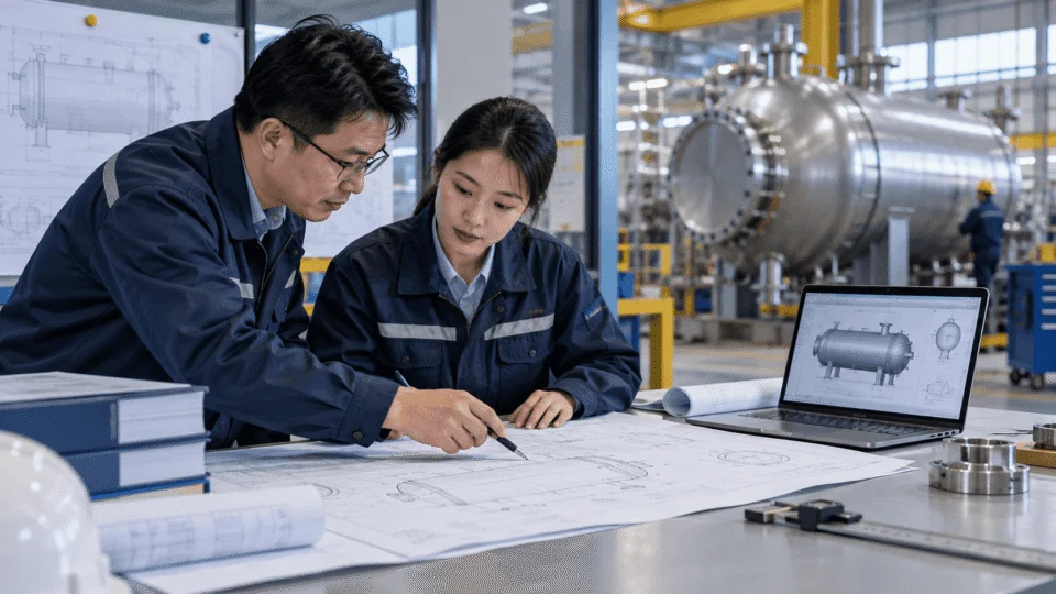
Codes and standards engineering reference
ENGINEERING WORKFLOW

From Process Data to Fabrication Drawing

A vessel does not move directly from required capacity to fabrication. Engineering develops through a sequence in which process requirements are converted into mechanical design inputs, calculations, reviews and finally controlled fabrication drawings.

PROCESS REQUIREMENTS

Define what the vessel must do

Process medium Required capacity Operating pressure Operating temperature Process function
↓
DESIGN CONDITIONS

Convert operation into design inputs

Design pressure Design temperature Vacuum condition Corrosion basis Applicable load cases
↓
MATERIAL & GEOMETRY

Build the vessel configuration

Material Diameter Length Head type Orientation
↓
MECHANICAL DESIGN

Evaluate the pressure boundary and supports

Shell Heads Openings Supports External-pressure stability
↓
ENGINEERING REVIEW

Check the complete equipment arrangement

Nozzle arrangement Maintainability Fabrication feasibility Code compliance Project specifications
↓
FABRICATION DRAWINGS

Translate engineering into controlled manufacturing information

Dimensions Materials & thicknesses Weld details Nozzle schedule Supports & internals Inspection requirements
ENGINEERING OUTPUT A vessel configuration that can be fabricated, inspected, installed and operated according to the defined project requirements.
Process Data → Mechanical Design → Engineering Review → Fabrication Drawing
PROJECT INPUT CHECKLIST

What Should You Send to the Vessel Manufacturer?

The more clearly the process and mechanical requirements are defined at the beginning, the more efficiently the vessel can be reviewed and engineered. You do not need to have every answer before contacting us — existing process data, specifications, sketches or preliminary drawings can be used as the starting point.

BASIC VESSEL INFORMATION

Define the equipment arrangement

Vessel function Vertical or horizontal orientation Required capacity Preferred diameter or dimensional limits Installation location
PROCESS CONDITIONS

Define the service condition

Process medium Operating pressure Operating temperature Design pressure, if specified Design temperature, if specified Vacuum condition, if applicable Liquid density, where relevant
MATERIAL REQUIREMENTS

Define the material basis

Preferred material Corrosion allowance Product-contact requirements Internal surface requirements Lining or coating requirements
CONNECTIONS & INTERNALS

Define what connects to the vessel

Nozzle list Manway requirements Instruments Agitator Coils Internal components Heating or cooling requirements
PROJECT REQUIREMENTS

Define the governing project rules

Applicable design code Wind or seismic conditions Inspection requirements NDE requirements Testing requirements Documentation requirements
EARLY-STAGE PROJECT?

Your Data Is Incomplete?

That is common during the early stage of many projects. Send us the information already available — process datasheets, sketches, equipment lists or preliminary drawings — and our team can review what additional vessel-design information is required.

EARLY-STAGE DESIGN RISKS

Common Early-Stage Design Mistakes

Many avoidable vessel-design changes begin with incomplete inputs or decisions made too late. Identifying the full service condition, installation environment and equipment interfaces early can reduce redesign, drawing revisions and fabrication changes later in the project.

PRESSURE BASIS

Using Working Pressure as the Only Pressure Input

Operating pressure and mechanical design pressure serve different purposes. The intended design basis should be confirmed before calculations and material thicknesses are finalized.

VACUUM CONDITION

Forgetting Possible External Pressure

A vessel can experience vacuum during draining, cooling, condensation, steaming or connection to a vacuum system even when normal operation is under positive pressure.

MATERIAL SELECTION

Selecting Material Before Defining the Medium

Material choice should follow an understanding of the process medium, temperature, corrosion environment, cleanliness requirements and service life expectations.

NOZZLE LAYOUT

Finalizing Nozzles Too Late

Late changes to nozzle size, location or function can affect reinforcement, local loads, piping arrangement, internals and fabrication drawings.

SITE CONDITIONS

Ignoring External and Installation Loads

Wind, seismic conditions, piping loads, support arrangement, access restrictions and transport limits should be considered before the vessel layout is locked.

SYSTEM INTEGRATION

Treating the Vessel as an Isolated Component

The vessel interacts with piping, foundations, platforms, instruments, agitators, utilities and the surrounding process system. Those interfaces influence the final equipment design.

DESIGN PRINCIPLE Good vessel design begins with good design inputs.
Complete Inputs → Earlier Decisions → Fewer Revisions → More Controlled Fabrication
VESSEL DESIGN BASICS FAQ

Frequently Asked Questions

These questions cover the most common early-stage concerns about pressure vessel design, materials, pressure conditions, geometry and project inputs.

What information is required to design a pressure vessel?

Typical starting information includes the process medium, capacity, operating and design pressure, operating and design temperature, material requirements, vessel orientation, nozzle requirements, vacuum conditions and applicable design code. Additional project data may be required depending on the service and installation.

Is vessel design pressure the same as operating pressure?

Not necessarily. Operating pressure describes the process operating condition, while design pressure is part of the mechanical design basis. The appropriate design value should be defined from the project requirements and applicable engineering rules.

Does higher pressure always require a thicker vessel?

Pressure is an important factor, but required thickness also depends on vessel diameter, temperature, material properties, geometry, corrosion allowance, fabrication factors and other design conditions.

Can a vessel designed for positive pressure also operate under vacuum?

Not automatically. Vacuum introduces external pressure and potential buckling, which requires a separate stability evaluation. A vessel that is adequate for internal pressure may still be unsuitable for vacuum service.

How does vessel diameter affect design?

Diameter influences pressure stresses, required wall thickness, external-pressure stability, vessel proportions, supports, transportation limits and fabrication. It should therefore be selected together with capacity and overall geometry.

Why do pressure vessel nozzles require reinforcement?

An opening interrupts the continuity of the pressure-retaining shell or head. The opening and surrounding material therefore need to satisfy the applicable mechanical design requirements, which may include reinforcement depending on the configuration.

Which material should I choose for my pressure vessel?

Material selection depends on the process medium, design temperature, corrosion conditions, cleanliness requirements, mechanical properties, fabrication requirements and project specifications. Material should be selected from the defined service conditions rather than by cost alone.

Which pressure vessel design code should be used?

The required code depends on the project, end-user specification, installation location and regulatory requirements. The applicable design basis should ideally be established before detailed mechanical design begins.

Can you review a vessel project if I only have preliminary process data?

Yes. Preliminary process data, sketches, datasheets, equipment lists or early drawings can be used to identify which additional mechanical design inputs are still required before detailed engineering proceeds.

Scroll to Top
DRAWING & FILE REVIEW

Send Your Drawings

Upload your drawings, datasheets or existing specifications. Our engineering team will review the files and respond with technical feedback.

Engineering Review

Drawings, specifications and process requirements

Confidential File Handling

Project files are used only for technical review and quotation

Faster Technical Feedback

Clearer inputs help us respond more accurately and efficiently

DRAWING & FILE REVIEW

Send Your Drawings

Upload your drawings, datasheets or specifications. Our engineering team will review your files and provide technical feedback.

Contact Form Demo (#3)
Project Protected NDA available
12h Response
ASME / PED
AFTER SUBMISSION
01 Review
→
02 Confirm
→
03 Quote
TECHNICAL QUOTATION

Get a
Technical Quote

Tell us what you need. Our engineering team will review your requirements and respond within 12 hours.

Engineered for Your Application

From concept to certified manufacturing

Global Compliance

ASME, PED and other international standards

Expert Support

Direct access to our engineering team

TECHNICAL QUOTATION

Get a Technical Quote

Tell us what you need. Our engineering team will review your requirements and respond within 12 hours.

Contact Form Demo
Project Protected NDA available
12h Response
ASME / PED
AFTER SUBMISSION
01 Review
→
02 Confirm
→
03 Quote