ChannelVessel Intelligent Equipment Co., Ltd. Contact Us
CUSTOM JACKETED REACTOR SYSTEMS

Jacketed Reactors Engineered Around Your Heating, Cooling and Mixing Requirements

Custom jacketed reactor vessels for chemical processing, pharmaceuticals, food production, cosmetics, resins and other batch processes requiring controlled heating, cooling, mixing, pressure or vacuum.
Approx. 50 L to 20,000 L+ custom capacities
Steam, hot water, thermal oil, chilled water or glycol
Vacuum, atmospheric or positive-pressure service
Designed from process data. Jacket type, agitation, pressure boundary, thermal duty and controls are reviewed as one system.
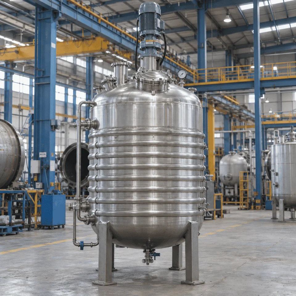
Industrial stainless steel jacketed reactor with half-pipe jacket
HEATING Steam · Hot Water · Thermal Oil
COOLING Water · Chilled Water · Glycol
PROCESS-DRIVEN THERMAL DESIGN

Temperature Control Starts With the Process

A jacketed reactor is not just a vessel with an outer heating or cooling chamber. Its thermal performance depends on how the utility, jacket, vessel wall, product and agitator work together as one system.

UTILITY SIDE

Heating or Cooling Medium

Steam, hot water, thermal oil, cooling water, chilled water or glycol provides the thermal driving force.

↓
HEAT-TRANSFER SURFACE

Jacket Geometry and Flow Path

Jacket type, channel geometry, circulation rate and pressure drop determine how effectively the utility reaches the vessel wall.

↓
PRESSURE BOUNDARY

Vessel Wall

Wall material, thickness, fouling and thermal conductivity all affect heat transfer into or out of the batch.

↓
PROCESS SIDE

Product + Agitation

The agitator must continuously move product across the heated or cooled wall. High viscosity can limit temperature uniformity even when jacket area is large.

THERMAL DUTY BEFORE JACKET TYPE

Heating and Cooling Duty Comes Before Jacket Selection

Selecting a jacket only by reactor volume can lead to poor temperature-control performance. The first question should be how much heat must be added or removed, and how quickly.

PROCESS INPUTS What defines the thermal load?
Batch mass Working volume × product density
Specific heat How much energy the product requires per degree
Temperature change Starting temperature to target temperature
Required batch time How quickly heating or cooling must be completed
Reaction heat Additional heat generated or absorbed during reaction
BATCH ENERGY REQUIREMENT
Qtotal = m × Cp × ΔT

Defines the total sensible heat required to move the batch from its starting temperature to the target temperature.

THEN
REQUIRED HEAT-TRANSFER RATE
Q̇ = Qtotal / t

Converts the total batch energy requirement into the heating or cooling duty required to meet the target batch time.

THEN
HEAT-TRANSFER PERFORMANCE
Q̇ = U × A × ΔTlm

Connects the required duty to heat-transfer area, temperature driving force and overall heat-transfer performance.

DESIGN OUTPUTS What the calculation influences
Jacket configuration Full / Dimple / Half-pipe / Combined
Required heat-transfer area Shell + Bottom head + Coil if required
Utility conditions Temperature · Pressure · Flow rate
Flow-path design Single zone or multiple zones
Agitation requirement Maintain product-side circulation
REAL-WORLD CORRECTIONS Actual performance depends on more than the equations.
Viscosity Agitation Fouling Utility Flow Pressure Drop Wall Thickness Thermal Conductivity Operating Temperature
!
ENGINEERING NOTE

“1,000 L reactor with a steam jacket” is not enough information for reliable thermal design. Batch conditions, target heating or cooling time and utility data should be defined before the jacket is finalized.

JACKET CONFIGURATION

Choose the Jacket Around the Process Conditions

There is no single jacket design that is ideal for every reactor. Utility pressure, circulation rate, required heat-transfer area, vessel size and process duty all influence the final configuration.
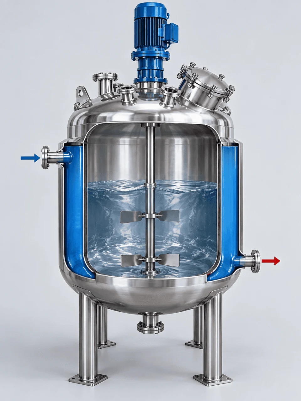
Conventional full jacket reactor configuration
CONVENTIONAL JACKET

Full Jacket

An outer shell creates a larger jacket chamber around the reactor body. It can suit many general-purpose heating and cooling duties using steam, water or thermal fluid.

Useful for General batch heating & cooling
Review carefully Jacket volume · flow pattern · pressure
Dimple jacket reactor configuration
DIMPLE JACKET

Lower Jacket Volume

The outer jacket is welded to the vessel at multiple points, creating a compact flow space that can provide good heat-transfer area with relatively low jacket volume.

Useful for Compact thermal-fluid circulation
Review carefully Jacket pressure · weld pattern · flow
Internal coil and combined heat-transfer reactor configuration
INTERNAL / COMBINED

Additional Heat-Transfer Area

Internal coils, bottom-head jackets or combined thermal surfaces can be considered when an external shell jacket alone does not provide enough heat-transfer capacity.

Useful for High thermal duty · limited ΔT
Review carefully Cleaning · internal access · process compatibility
SELECTION GUIDE Do not choose the jacket type from vessel volume alone.
Higher jacket pressure Consider a more defined pressure-capable flow path
Fast heat-up / cool-down Check duty, area, utility ΔT and circulation together
Large vessel Review circuit length and multi-zone jacket design
High-viscosity product Do not separate jacket selection from agitation design
JACKET + AGITATION

The Jacket and Agitator Must Work Together

A large heat-transfer surface does not guarantee fast or uniform temperature control. Heat transferred through the vessel wall still needs to be distributed through the batch by effective mixing.

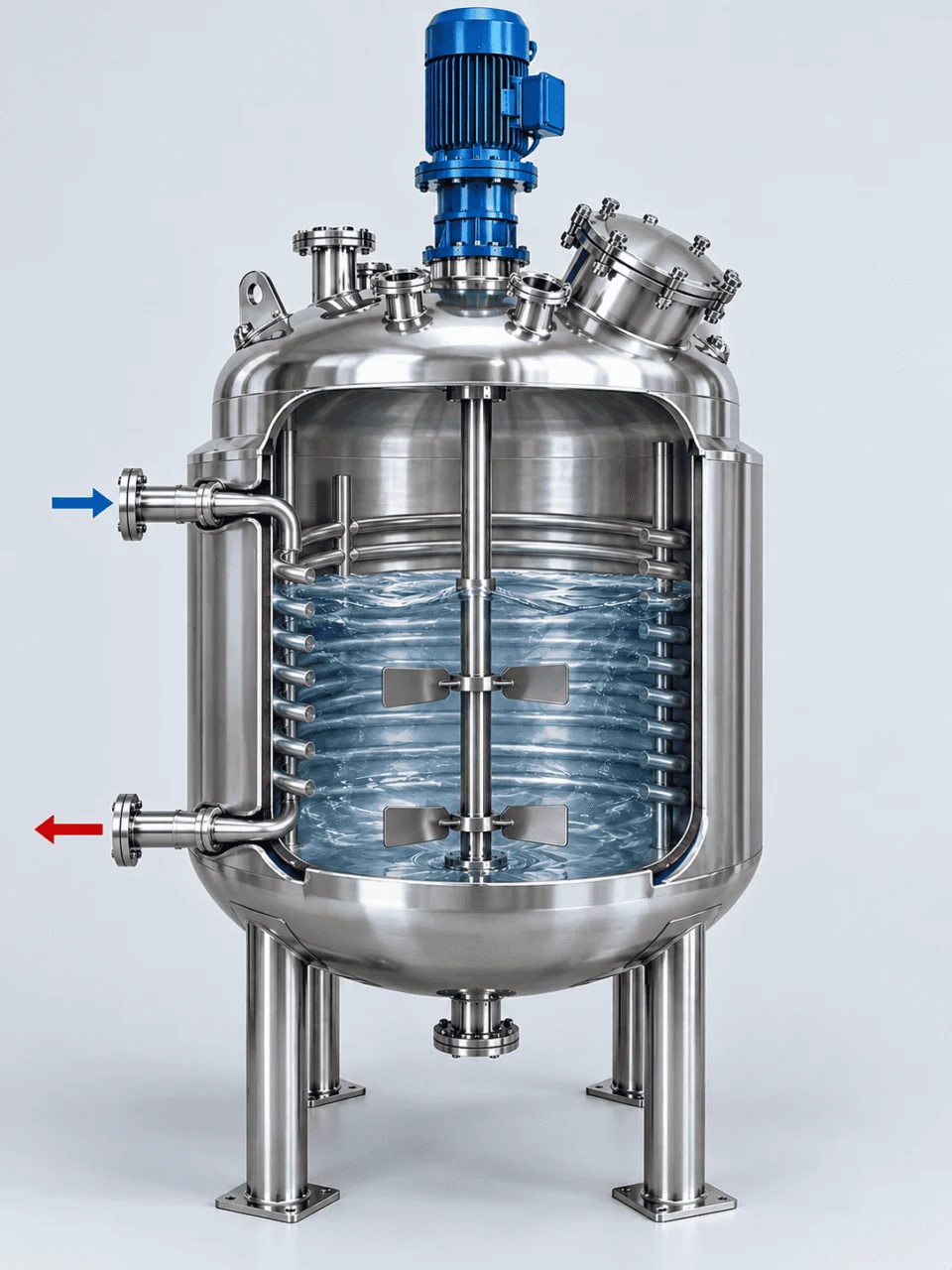
Jacketed reactor cutaway showing agitation and heat transfer circulation
A
HEAT ENTERS OR LEAVES AT THE WALL

Jacket performance depends on the product-side boundary layer.

Steam, thermal oil, cooling water or glycol can deliver strong utility-side performance, but heat still has to cross the vessel wall and move into the process fluid.

B
AGITATION RENEWS THE WALL FILM

Mixing continually replaces fluid near the heat-transfer surface.

Effective circulation reduces stagnant zones and helps move heated or cooled product away from the wall, replacing it with material from the bulk of the batch.

C
BULK TEMPERATURE BECOMES MORE UNIFORM

Viscosity and impeller selection directly affect thermal response.

As viscosity rises, product-side circulation becomes more difficult. In these services, jacket area and agitator design should be reviewed together rather than as separate equipment decisions.

MIXING SELECTION BY PROCESS BEHAVIOR Different products need different circulation patterns.
LOWER VISCOSITY

Propeller / Turbine

Useful where stronger bulk circulation and higher fluid movement are required.

GENERAL MIXING

Paddle

Can suit a wide range of moderate-viscosity blending and temperature-control duties.

HIGHER VISCOSITY

Anchor / Frame

Close-clearance designs can improve circulation near the vessel wall for viscous products.

TALLER VESSELS

Multiple Impellers

Multiple impeller levels may be used to maintain circulation throughout the full batch height.

!
DESIGN TOGETHER

Agitator type, speed, motor power, shaft, seal, impeller geometry and jacket performance should be evaluated as one reactor system.

JACKET ZONING

Single-Zone or Multi-Zone Jacket Design

Larger reactors do not always perform best with one jacket inlet and one outlet. Dividing the heat-transfer surface into separate circuits can improve utility distribution, reduce excessive flow-path length and provide more control over changing batch conditions.

EXAMPLE MULTI-ZONE ARRANGEMENT Separate thermal circuits can be assigned to different vessel areas.
ZONE A Upper Shell
ZONE B Middle Shell
UPPER SHELL
MIDDLE SHELL
LOWER SHELL
BOTTOM HEAD
ZONE C Lower Shell
ZONE D Bottom Head
Independent inlet / outlet paths
Shorter utility circuits
Better partial-batch flexibility
WHEN ZONING BECOMES USEFUL

Multi-zone construction should solve a process problem, not just add complexity.

Large vessel height

Long utility paths can create pressure-drop and flow-distribution issues.

Variable working volume

Different zones can remain active or inactive depending on actual batch level.

High thermal duty

Separate circuits can help maintain stronger circulation through the required heat-transfer area.

Different shell and bottom-head duty

Bottom heating or cooling may need to be controlled independently from the cylindrical shell.

SINGLE-ZONE STILL MAKES SENSE WHEN

The vessel is relatively compact, the utility circuit is short, batch level is consistent and one flow path can meet the required heat-transfer duty without excessive pressure drop.

TECHNICAL CONFIGURATION

Jacketed Reactor Technical Configurations

Final specifications are developed around the process rather than selected from a fixed catalog. Capacity, jacket type, agitation, pressure conditions, controls and auxiliary equipment can all be configured together.

Vessel Material Material of construction
SS304 · SS316L · Carbon Steel · SS321 · Special materials on request
Jacket Configuration Heat-transfer surface
Conventional jacket · Dimple jacket · Half-pipe / limpet jacket · Coil · Combined configuration
Heating Medium Heating utility
Steam · Hot water · Thermal oil · Electrically heated circulation system
Cooling Medium Cooling utility
Cooling water · Chilled water · Glycol · Compatible thermal fluid
Agitation Mixing system
Anchor · Frame · Paddle · Turbine · Propeller · Process-specific impeller arrangement
Drive System Motor and speed control
Fixed speed · Variable-frequency drive · Explosion-proof motor options
Shaft Sealing Process containment
Mechanical seal · Magnetic drive · Other process-appropriate sealing arrangement
Insulation & Cladding Thermal protection
Mineral wool · Polyurethane · Project-specified insulation · Stainless outer cladding
Controls Automation level
Manual controls · PID · PLC + HMI · Plant control system integration
Instrumentation Process monitoring
Temperature · Pressure · Level · Other project-specific instruments
Connections Nozzles and interfaces
Feed ports · Sight glass · Vent · Drain · Instrument nozzles · Custom process connections
Auxiliary Equipment Integrated process equipment
Condenser · Receiver · Vacuum system · Filters · Spray devices · Other auxiliary equipment
Hygienic Options Cleanability
Polished product-contact surfaces · Sanitary fittings · CIP · SIP where required
Documentation Project records
Inspection records · Pressure-test records · Material documentation · Project-specific documentation
MATERIALS & CONSTRUCTION

Materials and Construction Details Matter

Reactor material should be selected from the actual process medium, concentration, operating temperature, pressure, cleaning chemistry and contamination limits—not from vessel type alone.

MATERIAL SELECTION

Choose the material from the service conditions.

304
STAINLESS STEEL

SS304

Suitable for many general processing duties where corrosion conditions are relatively mild.

316L
STAINLESS STEEL

SS316L

Commonly selected for more demanding chemical, hygienic, pharmaceutical and food-contact service.

CS
CARBON STEEL

Carbon Steel

Can be suitable for non-corrosive industrial processes where stainless construction is unnecessary.

321+
SPECIAL SERVICE

SS321 & Other Materials

Available where temperature, corrosion or process conditions require a different material basis.

VERIFY BEFORE FINAL SELECTION

Product chemistry, concentration, operating temperature and cleaning media should all be reviewed before the material is finalized.

CONSTRUCTION DETAILS

Small mechanical details can strongly affect operation, cleaning and maintenance.

VESSEL ACCESS Manways, sight glasses and charging ports

Access points are positioned around filling, inspection, maintenance and cleaning requirements.

PROCESS CONNECTIONS Nozzles, dip pipes, vents, drains and instruments

Connection size and orientation should follow the P&ID, process sequence and maintenance access.

SHAFT SEALING Mechanical seal or magnetic-drive arrangement

Seal selection depends on pressure, temperature, shaft speed, leakage risk and product containment needs.

BOTTOM OUTLET Drainage should match product viscosity

Outlet geometry can be adjusted for free-flowing liquids, viscous products or low-residual-volume discharge.

INSULATION & CLADDING Thermal insulation with stainless outer finish

Insulation can reduce heat loss, improve temperature stability and protect personnel from hot surfaces.

HYGIENIC FINISH Polishing, sanitary fittings, CIP and SIP options

Cleanability requirements should be defined before fabrication so geometry and fittings can be coordinated properly.

MATERIAL REVIEW INPUTS What should be confirmed before fabrication?
Process medium
Concentration
Operating temperature
Cleaning chemicals
Contamination limits
Surface-finish requirement
THERMAL PERFORMANCE DIAGNOSTICS

Why Jacketed Reactor Temperature Control Can Underperform

Slow heating or cooling does not automatically mean the jacket is too small. Reactor performance can be limited by utility conditions, mixing, viscosity, fouling, flow-path design or the available temperature difference.

Jacketed reactor thermal performance diagnostic illustration
SLOW HEATING The batch takes too long to reach target temperature.
POSSIBLE CAUSES
Low utility temperature Insufficient utility flow High viscosity Fouling Poor wall-side circulation
WHAT TO CHECK

Verify steam or thermal-fluid condition, circulation rate, actual jacket flow path, agitator performance and the product-side heat-transfer resistance.

SLOW COOLING Cooling time is much longer than the process target.
POSSIBLE CAUSES
Warm cooling water Low chilled-water flow Reaction heat Insufficient area Fouling
WHAT TO CHECK

Compare the actual cooling-medium inlet temperature and flow with the design basis, then review heat-transfer area and any exothermic load remaining in the batch.

UNEVEN BATCH TEMPERATURE One sensor reaches target while the bulk batch remains non-uniform.
POSSIBLE CAUSES
Wrong impeller type Insufficient agitator speed Tall vessel geometry High viscosity Probe location
WHAT TO CHECK

Review circulation pattern, impeller diameter, impeller level, shaft speed and temperature-probe position instead of assuming one local reading represents the entire reactor.

HIGH JACKET PRESSURE DROP Utility circulation becomes difficult or pump demand rises.
POSSIBLE CAUSES
Long flow path Small channel area Excessive flow rate Complex routing
WHAT TO CHECK

Review channel geometry, circuit length and whether a multi-zone jacket would provide a shorter, more controllable utility path.

SLOW FINAL TEMPERATURE APPROACH Heating or cooling becomes progressively slower near the setpoint.
POSSIBLE CAUSES
Low remaining ΔT Utility limit Reduced driving force
WHAT TO CHECK

As product temperature approaches utility temperature, the driving force decreases. Target temperature, target time and utility temperature must therefore be reviewed together.

WHY THIS MATTERS

A larger jacket is not automatically the correct fix.

Before changing vessel size or adding heat-transfer area, check the complete thermal system: utility supply, jacket circulation, vessel wall, agitator performance, product viscosity and actual process duty.

ENGINEERING INPUTS

Designed From Your Process Data

A useful reactor inquiry should describe the process, not only the vessel capacity. The more clearly the operating conditions are defined, the more accurately the jacket, agitator, pressure boundary and control system can be configured.

WHAT TO SEND US

Start with the process conditions you already know.

VESSEL & PRODUCT
Working volume Total volume Process medium Density Viscosity Batch mass
THERMAL REQUIREMENT
Starting temperature Target temperature Heating time Cooling time Reaction heat
UTILITY CONDITIONS
Heating medium Heating pressure Heating temperature Cooling medium Cooling temperature Available flow rate
MECHANICAL & PROCESS
Operating pressure Vacuum condition Agitation requirement Preferred material Cleaning requirement Control requirement
MINIMUM USEFUL STARTING POINT

Capacity, process medium, operating temperature, operating pressure, heating or cooling medium, approximate viscosity and preferred material.

WHAT WE DEFINE FROM THE DATA

One set of process inputs drives multiple reactor decisions.

THERMAL DESIGN Heating / cooling duty and heat-transfer area
JACKET DESIGN Jacket type, flow path, pressure and zoning
AGITATION Impeller type, motor power, shaft and speed control
MECHANICAL DESIGN Vessel geometry, wall thickness, nozzles and supports
AUXILIARY SYSTEMS Condenser, receiver, vacuum, instruments and controls
INCOMPLETE DATA IS OK

If your process specification is incomplete, we can review the available information and identify which additional inputs are still needed before the reactor configuration is finalized.

HAVE A DATASHEET OR DRAWING? Send it directly for engineering review.
ENGINEERING SEQUENCE

From Process Requirement to Fabricated Reactor

A jacketed reactor should move through a defined engineering sequence before fabrication begins. Thermal duty, pressure boundary, agitation, nozzles and auxiliary systems need to be coordinated before the design is released to manufacturing.

PROCESS BASIS

Define the operating conditions

Capacity, product properties, pressure, vacuum, temperature, heating and cooling targets, utilities and mixing requirements are reviewed first.

OUTPUT Process design basis
THERMAL DESIGN

Establish heating and cooling duty

Required heat-transfer rate, utility conditions, jacket area, flow path and possible zoning are developed from the batch thermal requirement.

OUTPUT Jacket design basis
MECHANICAL DESIGN

Develop the pressure boundary

Vessel geometry, wall thickness, heads, nozzles, supports, jacket pressure, agitation loads and thermal effects are coordinated.

OUTPUT Mechanical configuration
SYSTEM INTEGRATION

Add the equipment around the vessel

Agitator, seal, condenser, receiver, vacuum system, instruments, control panel and plant interfaces are integrated with the reactor.

OUTPUT Complete reactor package
MANUFACTURING RELEASE

Freeze the design before fabrication

Drawings, material scope, inspection requirements, testing and documentation are confirmed before the manufacturing package is released.

OUTPUT Approved fabrication package
DESIGN REVIEW SHOULD CONNECT ALL SYSTEMS

The goal is not to manufacture a tank with a mixer and a jacket.

The goal is to deliver a reactor where the pressure boundary, heat-transfer system, agitation system and process connections function together under the actual operating conditions.

Pressure Boundary Pressure · Vacuum · Temperature
Heat Transfer Duty · Area · Utility · Zoning
Agitation Impeller · Torque · Shaft · Seal
Process Interfaces Nozzles · Instruments · Controls
FABRICATION & QUALITY CONTROL

Fabrication, Inspection and Testing

A jacketed reactor contains multiple welded assemblies, pressure boundaries and rotating components. Fabrication quality therefore needs to be controlled from material preparation through final testing and documentation.
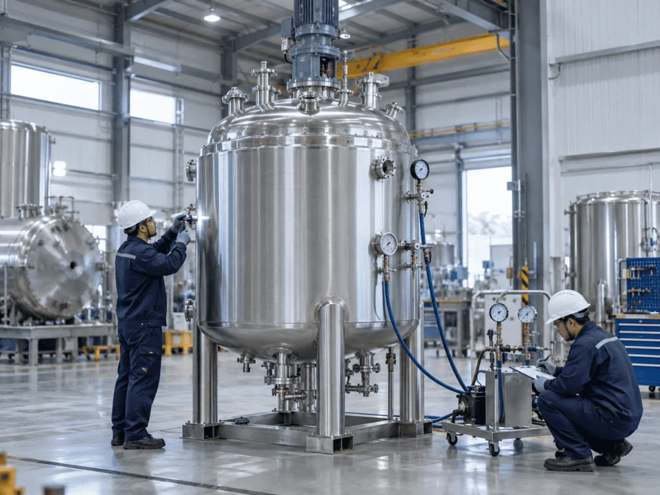
Jacketed reactor fabrication inspection and pressure testing in workshop
PROJECT QUALITY LEDGER What is controlled before the reactor leaves the factory.
Project-specific inspection plan
MATERIAL PREPARATION Material identification and preparation
CONTROL POINTS

Material grade, thickness, cutting, forming and component preparation are checked against the approved manufacturing scope.

PROJECT RECORD Material traceability / preparation records
WELDING & ASSEMBLY Pressure boundary and jacket fabrication
CONTROL POINTS

Shell seams, heads, jacket welds, nozzles, supports and agitator interfaces are assembled according to the approved fabrication drawings.

PROJECT RECORD Welding / dimensional inspection records
NDE / EXAMINATION Inspection methods matched to the project
CONTROL POINTS

Visual examination and additional NDE can be applied where required by the design specification, inspection plan or project documentation.

VT PT MT RT UT
PROJECT RECORD NDE reports where specified
PRESSURE / LEAK TEST Verify the completed pressure boundaries
CONTROL POINTS

The vessel and jacket can be pressure or leak tested according to the agreed design basis, test procedure and project requirements.

PROJECT RECORD Pressure-test / leak-test records
FUNCTIONAL CHECK Agitator and installed systems
CONTROL POINTS

Agitator rotation, drive condition, installed instruments, valves and agreed auxiliary functions can be checked before shipment.

PROJECT RECORD Trial-operation / functional-check records
FINAL RELEASE Documentation review before shipment
CONTROL POINTS

Final dimensions, equipment condition, agreed documentation and shipment scope are reviewed before the reactor is released.

PROJECT RECORD Final inspection dossier
DOCUMENTATION SHOULD BE DEFINED BEFORE FABRICATION

Inspection scope is easier to control when it is agreed before manufacturing starts.

Material Records Defined by project scope
Inspection Records Dimensional / visual / NDE as required
Test Records Pressure / leak / functional checks
Project Documents According to agreed documentation list
PROCESS APPLICATIONS

Jacketed Reactors Across Different Process Industries

The industry only tells part of the story. Product chemistry, viscosity, reaction heat, cleanliness, pressure and batch sequence determine how the reactor should actually be configured.

Chemical processing jacketed reactor
CHEMICAL PROCESSING

Synthesis, neutralization and polymerization

Reaction heat, corrosion, pressure or vacuum and changing viscosity can all affect the same batch.

DESIGN FOCUS Material compatibility · Heat removal · Pressure boundary · Seal selection
PHARMACEUTICAL

Controlled hygienic batch processing

Thermal performance must work together with cleanability, contamination control and repeatable process conditions.
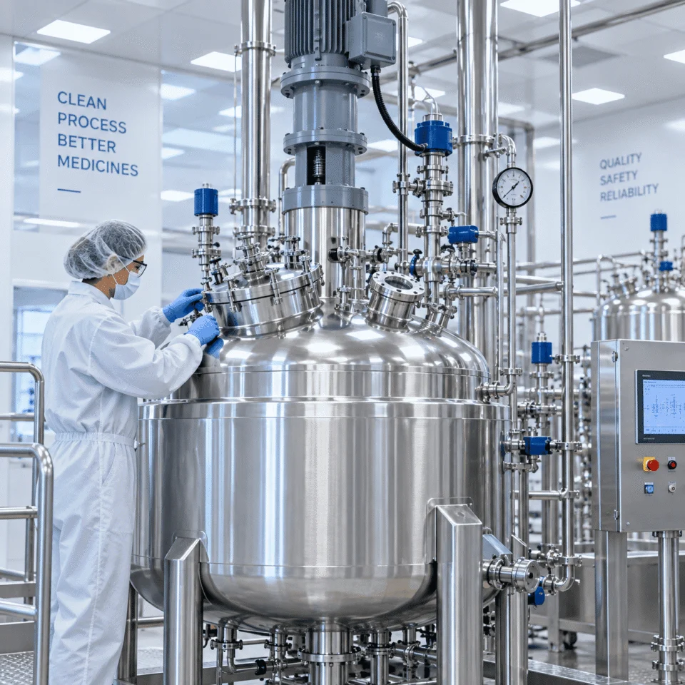
DESIGN FOCUS SS316L · Sanitary fittings · Polished surfaces · CIP / SIP
Pharmaceutical jacketed reactor
PROCESS CONDITIONS COME FIRST Two reactors in the same industry can still need completely different configurations.
Viscosity Reaction Heat Pressure / Vacuum Cleaning
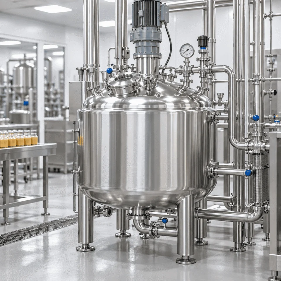
Food and beverage jacketed reactor
FOOD & BEVERAGE

Heating, cooling and blending

Product quality can depend on gentle mixing, uniform temperature, hygienic geometry and complete drainage.

DESIGN FOCUS Hygienic design · Wall circulation · Drainability · Temperature uniformity
COSMETICS & PERSONAL CARE

Creams, gels, lotions and shampoos

Viscosity can rise significantly during cooling, making wall-side circulation and discharge increasingly important.
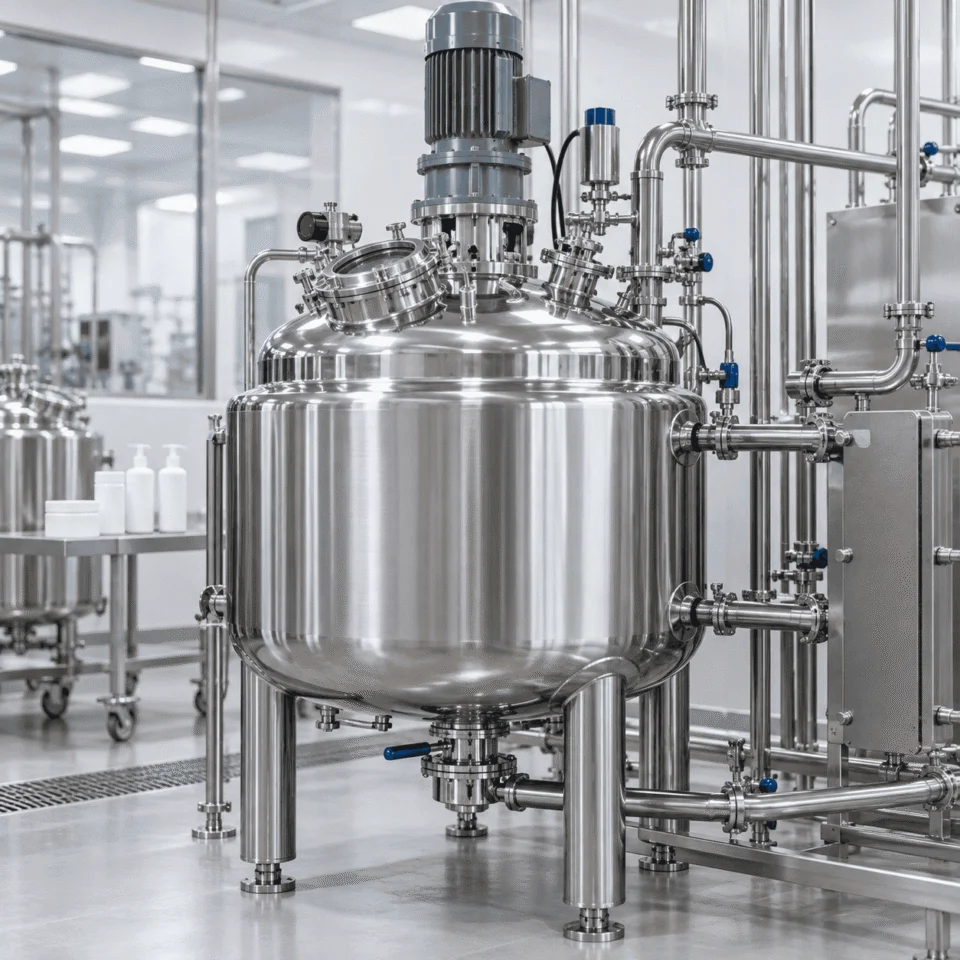
DESIGN FOCUS Anchor / frame · Variable speed · Wall heat transfer · Viscous discharge
Cosmetics and personal care jacketed reactor
Resins adhesives and polymers jacketed reactor
RESINS · ADHESIVES · POLYMERS

High-viscosity reaction service

Higher viscosity increases torque demand and can make heat removal, mixing uniformity and final discharge more difficult.

DESIGN FOCUS High torque · Close-clearance mixing · Thermal duty · Bottom outlet design
FERMENTATION & BIOPROCESS

Controlled biological processing

Stable temperature, sanitary construction, instrumentation and automated cleaning can all be required together.
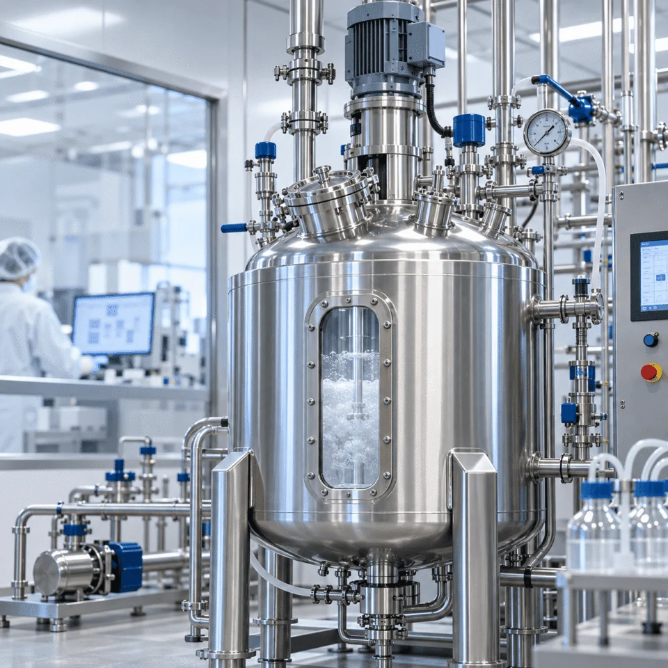
DESIGN FOCUS Temperature control · Instrumentation · Sanitary geometry · CIP / SIP
Fermentation and bioprocess jacketed reactor
ENGINEERING FAQ

Frequently Asked Questions About Jacketed Reactors

These questions cover the issues that most often affect jacket selection, heating and cooling performance, pressure or vacuum operation, materials and controls.

Which jacket type is best for a reactor?

There is no universally best jacket. The appropriate configuration depends on vessel size, required heating or cooling duty, utility pressure, utility flow, allowable pressure drop, temperature range and fabrication requirements. A conventional jacket may suit one process, while another may benefit from a dimple or half-pipe configuration.

Can a jacketed reactor operate under vacuum?

Yes. A reactor can be engineered for vacuum operation when required by the process. Vacuum design affects the shell, heads, nozzles, supports and other structural details, so the vacuum condition should be defined during the design stage.

Can the same jacket be used for heating and cooling?

In many systems, the same jacket circuit can be used with different thermal media at different stages of the batch. The operating sequence, media compatibility, pressure, temperature, drainage and control strategy still need to be reviewed. Some processes may benefit from separate circuits or zones.

Can steam and chilled water be used in the same reactor?

Yes, depending on the system design. The transition between heating and cooling media should consider pressure, drainage, thermal shock and control requirements.

How do you determine the required jacket area?

Required heat-transfer area depends on thermal duty, available temperature difference and the overall heat-transfer coefficient. Actual design also considers viscosity, mixing, fouling, jacket geometry, utility flow and vessel-wall construction. Capacity alone is not enough to determine jacket area.

Does a larger jacket always provide faster heating?

No. Increasing heat-transfer area can help, but performance may still be limited by utility flow, utility temperature, product viscosity, agitation, fouling or heat transfer through the vessel wall. The complete thermal system should be reviewed.

Can you build a reactor for high-viscosity material?

Yes. High-viscosity applications require particular attention to agitator geometry, motor torque, shaft design, wall clearance, heat transfer and discharge. Anchor, frame or other low-speed, high-torque mixing arrangements may be considered according to the product.

What materials are available?

Common options include SS304, SS316L and carbon steel. SS321 and other materials can also be considered where process conditions require them. Final material selection should be based on the actual chemical medium, concentration, temperature and corrosion conditions.

Can you manufacture from our existing drawing?

Yes. ChannelVessel can review customer drawings, datasheets and process requirements and manufacture customized reactor equipment accordingly. Where necessary, the design can also be revised to suit process, fabrication or project conditions.

Can you provide PLC controls?

Yes. Depending on the project, the reactor can be supplied with manual controls, PID temperature control, PLC + HMI control or provisions for integration with the customer's plant control system. Instrumentation and automation scope can be customized.

How is a jacketed reactor tested before shipment?

Testing depends on the equipment design and project specification. Typical inspection can include dimensional checks, pressure or leak testing, agitator trial operation, functional checks and documentation review. Additional inspection requirements can be agreed before fabrication.

CUSTOM JACKETED REACTOR ENGINEERING

Build the Reactor Around the Process — Not the Other Way Around

Send ChannelVessel your process data, equipment specification or existing drawing. We can review the required capacity, heating and cooling duty, jacket configuration, agitation system, pressure conditions, materials and auxiliary equipment before the final reactor configuration is developed.

ENGINEERING REVIEW One process requirement. One coordinated reactor design.
THERMAL SYSTEM Jacket + duty + utility + agitation
MECHANICAL SYSTEM Pressure boundary + material + nozzles
PROJECT PACKAGE Fabrication + testing + documentation
Scroll to Top
DRAWING & FILE REVIEW

Send Your Drawings

Upload your drawings, datasheets or existing specifications. Our engineering team will review the files and respond with technical feedback.

Engineering Review

Drawings, specifications and process requirements

Confidential File Handling

Project files are used only for technical review and quotation

Faster Technical Feedback

Clearer inputs help us respond more accurately and efficiently

DRAWING & FILE REVIEW

Send Your Drawings

Upload your drawings, datasheets or specifications. Our engineering team will review your files and provide technical feedback.

Contact Form Demo (#3)
Project Protected NDA available
12h Response
ASME / PED
AFTER SUBMISSION
01 Review
→
02 Confirm
→
03 Quote
TECHNICAL QUOTATION

Get a
Technical Quote

Tell us what you need. Our engineering team will review your requirements and respond within 12 hours.

Engineered for Your Application

From concept to certified manufacturing

Global Compliance

ASME, PED and other international standards

Expert Support

Direct access to our engineering team

TECHNICAL QUOTATION

Get a Technical Quote

Tell us what you need. Our engineering team will review your requirements and respond within 12 hours.

Contact Form Demo
Project Protected NDA available
12h Response
ASME / PED
AFTER SUBMISSION
01 Review
→
02 Confirm
→
03 Quote