
ChannelVessel Intelligent Equipment Co., Ltd. Contact Us
Custom Stainless Steel Reactor Vessels

Stainless Steel Reactors Engineered Around Your Process

Custom reactor vessels engineered for chemical reactions, mixing, heating, cooling, pressure and vacuum processing. We design around your medium, viscosity, temperature, pressure and heat-transfer duty—not just tank capacity.
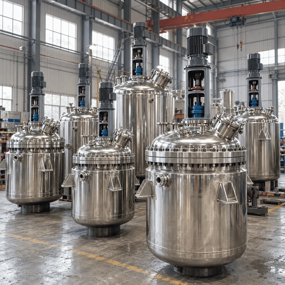
SS304 / SS316 / SS316L Pressure & Vacuum Heating & Cooling Custom Agitation
✓ Larger volumes, higher pressure and special configurations can be reviewed project by project.
Custom stainless steel reactors manufactured by ChannelVessel
Custom Engineered to Process
Working Volume 50–20,000 L
Typical Pressure -0.1 to 1.0 MPa
Typical Temperature 0–160°C
Main Materials 304 / 316 / 316L
PROCESS-DRIVEN ENGINEERING

A Reactor Should Be Designed Around the Reaction

Capacity alone does not define a reactor. The final vessel geometry, agitation, heat-transfer system, pressure boundary and material selection should follow the actual operating conditions.

Your Process Conditions
Process Medium

Chemistry, corrosion and contamination requirements.

Working Volume

Batch size, headspace, foaming and vapor disengagement.

Viscosity

Initial, operating and end-of-batch viscosity range.

Solids Content

Powders, crystals, catalysts and suspension duty.

Temperature

Operating temperature, heat-up and cooling cycles.

Pressure & Vacuum

Internal pressure, vacuum cycles and jacket pressure.

Heating & Cooling

Steam, hot water, thermal oil, chilled water or glycol.

Mixing Objective

Blending, suspension, dispersion, dissolution or circulation.

ENGINEERING REVIEW Process + Mechanical Design

We translate the operating data into a reactor configuration that can be fabricated, operated and maintained.

→
What the Data Changes
Vessel & Material

Geometry, working volume, SS304 / SS316 / SS316L, surface finish and corrosion strategy.

Agitation System

Impeller type, shaft arrangement, speed, motor power, torque and baffle configuration.

Heat-Transfer System

Jacket, half-pipe, internal coil, utility flow path and required transfer area.

Mechanical Design

Pressure, vacuum, nozzle reinforcement, supports, sealing and structural loads.

Quick Distinction Reactor vs. Mixing Tank vs. Storage Tank
Working Volume 50–20,000 L
Typical Pressure -0.1 to 1.0 MPa
Typical Temperature 0–160°C
Agitation 20–200 rpm
Surface Finish Down to Ra ≤0.4 μm
REACTOR CONFIGURATION

Choose the Reactor Structure Around the Process Duty

The vessel shell, heat-transfer surface, pressure boundary and agitation system should work as one engineered package. Different reaction duties need different reactor structures.

Stainless steel reactor configuration examples including jacketed, coil, pressure, vacuum and agitated reactor designs
Select a configuration Six common reactor structures
AGITATION ENGINEERING

The Agitator Is Selected for the Process — Not From a Standard List

Reactor volume alone cannot determine the impeller. Viscosity, solids loading, heat-transfer duty, gas dispersion, circulation pattern and the required process result all change the agitation system.

What we evaluate first Material Behavior Before Impeller Type

The same 2,000 L vessel can require a completely different agitator depending on whether the process is low-viscosity blending, solids suspension, high-viscosity circulation or heat-transfer control.

Viscosity Changes torque, speed and flow pattern
Solids Loading Changes suspension and settling behavior
Heat Transfer Changes wall-side circulation demand
Gas / Liquid Contact Changes shear and dispersion requirement
Typical Industrial Agitation Range 20–200 rpm
High viscosity / high torque General mixing Higher circulation

High-speed dispersion and high-shear systems are engineered separately. Typical drive configurations may range from approximately 1.1–11 kW and above depending on vessel size and process duty.

Mixing Objective From process goal to impeller concept
Low-viscosity circulation Propeller
Strong axial flow
General mixing / suspension Pitched-Blade Turbine
Balanced axial + radial flow
Dispersion / gas contact Turbine
Higher shear and dispersion
Moderate-viscosity duty Paddle
Broad bulk movement
Viscous wall-side circulation Anchor
Moves product close to vessel wall
Higher-viscosity bulk flow Helical Ribbon
Strong whole-vessel circulation
Combined Mixing Systems

Anchor + high-shear mixer, turbine + propeller or other combinations can be engineered when one impeller cannot achieve the required process result.

Stainless steel reactor agitation systems including propeller, turbine, paddle, anchor and helical ribbon mixers
Engineering Rule Impeller + Shaft + Motor + Vessel = One System

Shaft length, torque, gearbox weight, dynamic loads, nozzle reinforcement and support design are reviewed together.

Related Product Mixing Tanks Explore dedicated blending and mixing equipment →
THERMAL CONTROL

Heating & Cooling Around the Reaction

Reactor temperature control is not simply a matter of adding a jacket. The thermal system should be engineered around heat-up time, reaction heat, cooling duty, utility conditions, product viscosity and available heat-transfer area.

HEAT IN Steam · Hot Water · Thermal Oil
REACTION ZONE Controlled Thermal Duty

Heat transfer + agitation + process conditions

HEAT OUT Chilled Water · Cooling Water · Glycol
Heat-Transfer Structures Select the surface according to duty
Conventional Jacket

A versatile solution for many batch processes using steam, hot water, thermal oil, chilled water or glycol.

Dimple Jacket

A compact jacket structure that can provide useful heat-transfer area while keeping the vessel exterior relatively clean.

Half-Pipe Coil

Creates a defined utility flow path around the shell and can be applied where higher utility-side pressure or demanding thermal duty is involved.

Internal Coil

Adds heat-transfer area inside the vessel when the available external jacket area alone cannot satisfy the process requirement.

Stainless steel reactor heating and cooling system showing jacket, half-pipe jacket and internal coil configurations
Steam Hot Water Thermal Oil Chilled Water Glycol
Important Reactor pressure and jacket pressure are separate design conditions.

The vessel chamber and the heating/cooling circuit may operate at completely different temperatures and pressures.

What Actually Determines Thermal Performance? Six engineering checks before fabrication
Heat-Up Time

How quickly must the batch reach the target temperature?

Cooling Duty

Exothermic reactions may require rapid heat removal, not just temperature holding.

Heat-Transfer Area

Larger vessel volume does not automatically provide enough transfer surface.

Utility Conditions

Steam pressure, oil temperature, coolant temperature and flow rate all affect duty.

Product Viscosity

High-viscosity products can reduce wall-side heat transfer if circulation is weak.

Agitation

Good circulation helps reduce local temperature gradients and improves wall-side transfer.

Related Engineering Jacketed Pressure Vessels Explore jacket configuration, pressure boundary and heat-transfer design →
MATERIAL SELECTION

Select Stainless Steel From the Process Chemistry

Stainless steel grade should be selected from the actual process medium, temperature, chloride level, cleaning chemistry, contamination sensitivity and fabrication requirements—not simply from a standard material list.

Stainless steel reactor material and surface finish details for SS304, SS316 and SS316L
Material is only one layer Surface finish, weld treatment and cleaning requirements matter too.
Process Conditions
Acids / Alkalis Chlorides Temperature Cleaning Media Purity Requirement Pressure & Welding
ENGINEERING REVIEW Corrosion + Fabrication + Surface Requirement

Material selection is reviewed together with welding, pressure boundary, surface finishing and process compatibility.

SS304
General Industrial Service

A widely used stainless steel grade for many industrial processes with moderate corrosion requirements.

SS316
Improved Corrosion Resistance

Selected where the process environment is more demanding and improved resistance is required.

SS316L
Welding + Hygienic Applications

Frequently selected where corrosion resistance, welding performance and high-quality internal surfaces are important.

Special
Corrosion-Resistant Alloys

Duplex stainless steel, titanium, Hastelloy and other alloys can be evaluated when standard stainless steels are not suitable.

SURFACE FINISH OPTIONS Match the finish to the cleanliness and process requirement
General Industrial Mechanical Finish

Pickling, passivation and project-specific weld treatment.

Hygienic Service Ra ≤0.8 μm

Improved internal cleanability for hygienic processing duties.

High-Finish Option Ra ≤0.4 μm

For demanding hygienic or high-purity applications.

Optional Treatment Electropolishing

Available where enhanced surface quality is specified.

MECHANICAL DESIGN

Pressure, Vacuum & Mechanical Loads Must Be Reviewed Together

A reactor can experience internal pressure, full vacuum, jacket pressure, agitator torque, piping loads and thermal expansion during the same operating cycle. The vessel must be engineered as one mechanical system.
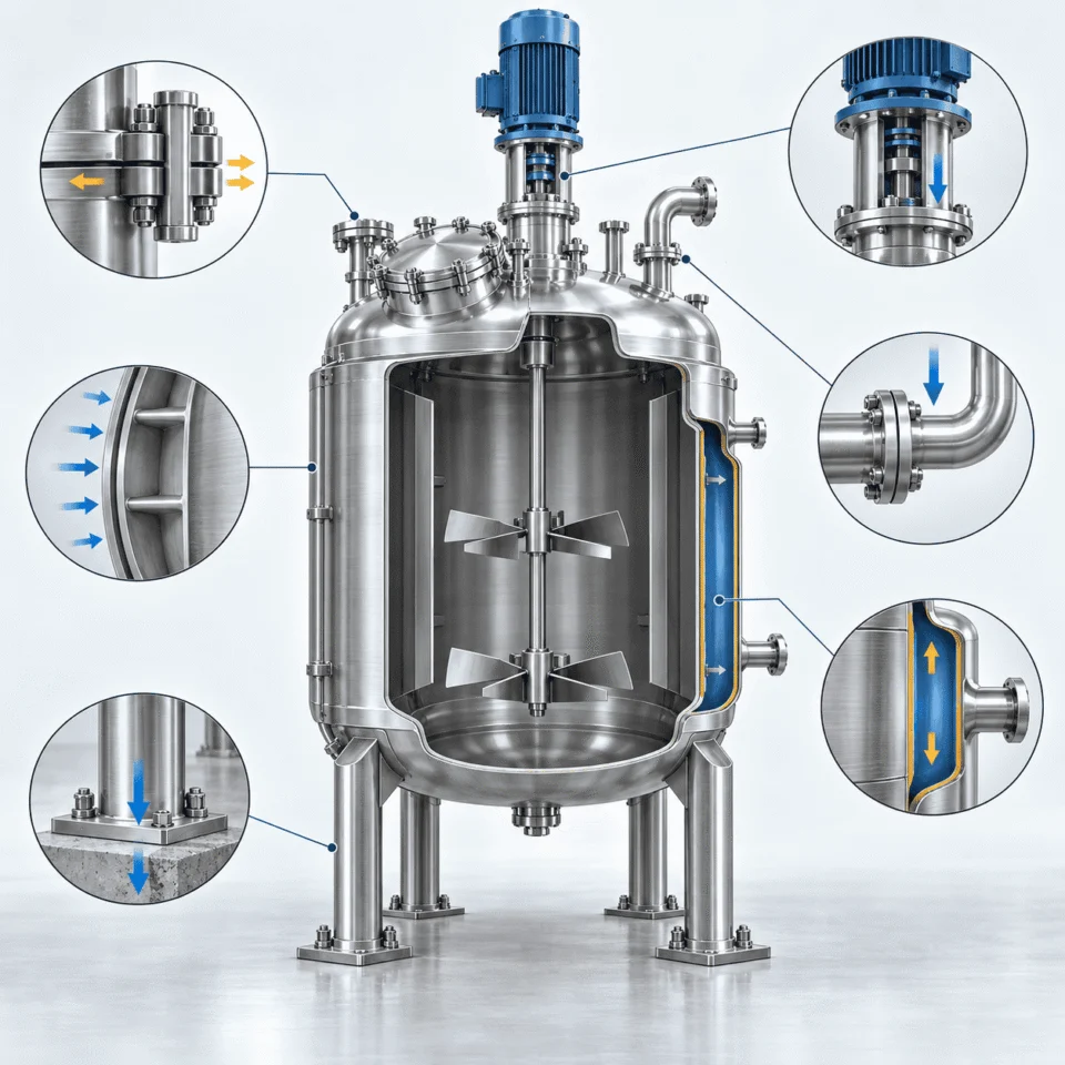
Internal Pressure Shell · Heads · Flanges
→
Vacuum Loading Stability · Stiffening
→
Dynamic Loads Agitator · Nozzles
→
Final Support Legs · Lugs · Skirt
Stainless steel reactor pressure, vacuum and mechanical design cutaway illustration
Typical Vessel Pressure -0.1 to 1.0 MPa
Pressure Direction Internal + External
Pressure Boundary Internal pressure changes more than shell thickness.

Pressure affects shell and head thickness, flanges, nozzles, reinforcement, agitator sealing, bolting and support design. Typical stainless steel reactor projects can be engineered up to approximately 1.0 MPa, with higher-pressure configurations reviewed separately.

Vacuum Stability External pressure creates a different failure mode.

Full vacuum down to approximately -0.1 MPa gauge requires review of shell geometry, unsupported length, wall thickness, roundness, stiffening and repeated vacuum cycles.

Separate Pressure Systems Reactor pressure and jacket pressure are not the same condition.

The process chamber and heating or cooling jacket can operate at different pressure and temperature combinations. Each boundary is checked independently.

Operating Cycles Pressure and vacuum may alternate during one batch.

Charging, reaction, distillation, transfer, cooling and cleaning can expose the vessel to very different mechanical conditions. The full operating sequence should be defined before fabrication.

Beyond Pressure Additional loads that can change the reactor design
Agitator Loads Torque · Shaft Loads · Vibration · Gearbox Weight

The agitator drive introduces static and dynamic loads into the vessel roof and support structure.

Nozzle & Piping Loads External Forces · Moments · Reinforcement

Large connected piping can introduce loads that must be considered at the nozzle-to-shell connection.

Support Design Legs · Lugs · Skirts · Platform Integration

Support type depends on vessel geometry, operating weight, agitator loads and installation conditions.

Thermal Expansion Vessel · Jacket · Piping · Supports

Heating and cooling cycles can create differential movement that should be considered before layout is finalized.

CUSTOM ENGINEERING DETAILS

Build the Reactor Around the Process Connections

A reactor is rarely an isolated vessel. Agitation, feeding, instrumentation, cleaning, sampling, discharge and utility connections should be coordinated before fabrication so the final layout works as one process system.

Agitator Drive Top / Bottom / Project-Specific

Drive position is coordinated with vessel geometry, torque, maintenance access and process requirements.

Mechanical Seal Single / Double / Special Seal

Selected according to pressure, vacuum, leakage control and media compatibility.

Manway Inspection & Maintenance Access

Size and position are arranged for cleaning, internal inspection and maintenance.

Feed Connections Liquid · Powder · Gas · Additives

Multiple feed nozzles can be integrated around the process sequence and piping layout.

CIP Connection Spray Device Integration

Cleaning connections can be arranged for hygienic or repeatable internal cleaning duties.

Stainless steel reactor engineering details including agitator drive, seal, nozzles, sampling, sight glass and bottom outlet
Layout Principle Nozzle placement should follow process flow, not empty space.
Temperature Measurement Thermowell + Sensor

Sensor position is selected to represent actual process temperature rather than simply vessel-wall temperature.

Pressure Instrumentation Gauge · Transmitter · Safety Device

Pressure connections can be integrated according to operating and safety requirements.

Sight Glass Visual Process Observation

Inspection windows can be added where product behavior and operating conditions allow.

Sampling Port Process / Hygienic Sampling

Sampling arrangement is selected according to cleanliness, pressure and operator access.

Bottom Outlet Low-Residue Discharge

Flush-bottom and low-hold-up configurations can be evaluated where complete discharge is important.

Supporting Systems Connections around the reactor can be integrated into the same project scope.
Jacket Connections Inlet · Outlet · Vent · Drain

Utility connections are arranged around the selected jacket or coil flow path.

Insulation Rock Wool · PU · Project-Specific

Applied for thermal retention, cooling stability or personnel protection.

Speed Control VFD Agitator Control

Variable-speed control can be integrated where mixing duty changes during the batch.

Automation PID · PLC · Local Panel

Temperature, pressure, speed and process signals can be integrated into the control scope.

Electrical Explosion-Proof Options

Electrical configuration can be specified for project and installation requirements.

APPLICATIONS

Reactor Design Changes With the Industry

The same stainless steel reactor shell can require very different materials, agitation, heat transfer, sealing, instrumentation and surface finishing depending on the process industry.

Chemical Processing Resins · Adhesives · Coatings · Additives · Intermediates
Typical Process Needs

Reaction control, corrosion resistance, solvent compatibility, heating and cooling, pressure or vacuum, and engineered agitation.

Design Focus Corrosion + Thermal Duty + Mixing
→
Petrochemical Processing Process Chemicals · Additives · Intermediates
Typical Process Needs

Pressure-rated construction, controlled temperature, mechanical reliability, compatible sealing and process instrumentation.

Design Focus Pressure + Sealing + Reliability
→
Pharmaceutical Processing Synthesis · Blending · Controlled Batch Processing
Typical Process Needs

High-quality stainless steel surfaces, cleanability, hygienic connections, controlled processing and detailed project documentation.

Design Focus Finish + Cleanability + Control
→
Food & Beverage Heating · Cooling · Mixing · Hygienic Processing
Typical Process Needs

Hygienic product contact surfaces, controlled temperature, low-hold-up discharge, CIP capability and repeatable batch conditions.

Design Focus Hygiene + Thermal Control + Cleaning
→
Advanced Materials Slurries · Powders · High-Purity Media · Specialty Materials
Typical Process Needs

Vacuum processing, solids suspension, contamination control, controlled temperature and specialized agitation for changing material behavior.

Design Focus Purity + Solids Handling + Agitation
•
Engineering Principle

Industry name alone is not enough to size or configure a reactor. The actual process medium, viscosity, solids content, pressure, temperature, heat-transfer duty and cleaning requirement remain the primary design inputs.

FABRICATION & QUALITY CONTROL

Engineering Continues Through Fabrication

A good reactor design still depends on controlled manufacturing. Material identity, forming, welding, inspection, testing, surface treatment and final documentation all affect the finished vessel.
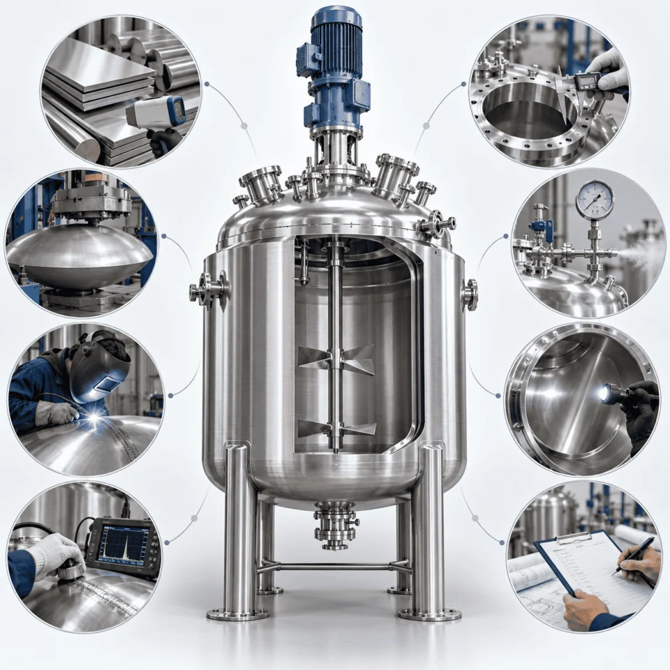
Material Verification
Shell & Heads Forming
Pressure Boundary Welding
Critical Joints NDT
Assembly Dimensional Check
Pressure Boundary Testing
Final Stage Finish & Documents
Stainless steel reactor fabrication, inspection and testing process
Manufacturing Principle Inspect the vessel before the next step hides the evidence.

Material, welds, nozzle locations and test results are easier to verify when quality checks are built into the fabrication sequence.

QUALITY GATE What Gets Checked During Fabrication
Project-Specific Inspection Plan
✓
Material Verification Grade, certificates and project traceability

Material identity and supporting documentation are reviewed before fabrication begins.

✓
Welding Control Joint preparation, procedure and weld quality

Shell seams, head joints, nozzles, jackets, coils, supports and agitator mounting areas receive process-specific attention.

✓
Nondestructive Examination NDT according to code and project requirements

Examination scope and method are selected according to the pressure boundary, applicable standard and project criticality.

✓
Dimensional Inspection Nozzle orientation, supports and assembly interfaces

Key dimensions are checked before shipment so the vessel can connect correctly to piping, platforms and surrounding equipment.

✓
Pressure & Leak Testing Vessel, jacket and vacuum integrity

Testing can include hydrostatic, pneumatic where appropriate, jacket, leak and vacuum tests according to the design and purchase specification.

✓
Surface Treatment Finish quality matched to the service requirement

Mechanical polishing, pickling, passivation, electropolishing and project-specific external finishing can be incorporated.

Final Documentation The vessel should leave the factory with more than a finished surface.
Approved Drawings Material Documents Inspection Records Pressure Test Records Manufacturing Documents Project-Specific Reports
PROJECT INPUT

Send the Process Conditions — We Will Work From There

You do not need a complete mechanical specification before contacting us. A few process conditions are usually enough to begin reactor configuration and quotation.

Process What happens inside the vessel?
Product / Chemical Medium Batch Size Working Volume Density Viscosity Range Solids Content Mixing Objective
Temperature How should the batch be heated or cooled?
Operating Temperature Design Temperature Heating Requirement Cooling Requirement Available Utility
Pressure What pressure conditions occur during the batch?
Operating Pressure Design Pressure Vacuum Requirement Jacket Pressure
Material & Finish What must the product-contact surface withstand?
Preferred Material Corrosion Information Surface Finish Cleaning Requirement
Connections What needs to connect to the reactor?
Feed Nozzles Bottom Outlet Manway Sampling CIP Vent Instrumentation
Useful Documents Send anything you already have
P&ID Process Data Sheet Existing Reactor Drawing Equipment Specification Nozzle Schedule Plant Layout Reference Photo
FREQUENTLY ASKED QUESTIONS

Common Questions Before Reactor Design

READY FOR ENGINEERING REVIEW?

Start With the Process — We’ll Build the Reactor Around It.

Scroll to Top
DRAWING & FILE REVIEW

Send Your Drawings

Upload your drawings, datasheets or existing specifications. Our engineering team will review the files and respond with technical feedback.

Engineering Review

Drawings, specifications and process requirements

Confidential File Handling

Project files are used only for technical review and quotation

Faster Technical Feedback

Clearer inputs help us respond more accurately and efficiently

DRAWING & FILE REVIEW

Send Your Drawings

Upload your drawings, datasheets or specifications. Our engineering team will review your files and provide technical feedback.

Contact Form Demo (#3)
Project Protected NDA available
12h Response
ASME / PED
AFTER SUBMISSION
01 Review
→
02 Confirm
→
03 Quote
TECHNICAL QUOTATION

Get a
Technical Quote

Tell us what you need. Our engineering team will review your requirements and respond within 12 hours.

Engineered for Your Application

From concept to certified manufacturing

Global Compliance

ASME, PED and other international standards

Expert Support

Direct access to our engineering team

TECHNICAL QUOTATION

Get a Technical Quote

Tell us what you need. Our engineering team will review your requirements and respond within 12 hours.

Contact Form Demo
Project Protected NDA available
12h Response
ASME / PED
AFTER SUBMISSION
01 Review
→
02 Confirm
→
03 Quote