
ChannelVessel Intelligent Equipment Co., Ltd. Contact Us
ASME-Certified Separation Equipment

Separators & Filter Vessels

We design and fabricate ASME-certified separators and filter vessels — including gas-liquid separators, oil-water separators, filter vessels, and custom separation systems — for process pressures from full vacuum to 10 MPa, using carbon steel, 304/316L stainless steel, duplex steel, and lined carbon steel.

Built for real process separation duties Wet gas, oily wastewater, solid particles, liquid carryover, mist removal, and three-phase oil/gas/water streams.
Custom internals matched to the medium Wire mesh demisters, vane packs, CPI plates, filter bags, cartridges, baffles, and inlet devices.
Factory testing before delivery Material traceability, dimensional checks, NDE, hydrostatic testing, and export documentation can be supplied.
Separators and filter vessels manufactured by ChannelVessel
ASME U-Stamp Pressure vessel fabrication for export projects.
PED-CE Available Documentation support for European pressure equipment projects.
100% Factory Test Hydrostatic testing and inspection before shipment.
Gas-Liquid
Oil-Water
Filter Vessels
Custom Systems
Equipment Definition

What Are Separators and Filter Vessels?

Separators and filter vessels are pressure-rated process equipment that remove one phase or contaminant from a flowing stream — liquid droplets from gas, oil from water, or solid particles from liquid — using gravity, coalescence, centrifugal force, or filtration media.

In simple terms

A separator helps different phases settle, collect, or leave through different outlets. A filter vessel uses replaceable media, such as filter bags or cartridges, to capture particles from liquid or gas streams.

Our separation equipment scope includes four main types: gas-liquid separators, oil-water separators, filter vessels, and custom separation systems. They are used in oil & gas, chemical processing, water treatment, compressed air systems, petrochemical plants, utilities, and general process lines where stable downstream operation depends on cleaner gas, cleaner water, or cleaner liquid.

Equipment Covered Below Choose the separation duty first, then review the detailed product type below.
Product Family

Separators and Filter Vessels Built for Different Separation Duties

Our separators and filter vessels are grouped by separation duty, so engineers can quickly choose the right equipment based on medium, flow rate, pressure, contaminant type, and outlet quality requirement.

Choose by the duty, not only by the vessel name.

Wet gas, oily water, solid particles, and mixed gas/oil/water streams need different vessel layouts, internals, residence time, and maintenance access.
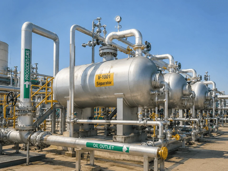
Gas-liquid separator manufactured by ChannelVessel
Wet Gas / Vapor 01

Gas-Liquid Separators

For wet gas, vapor streams, and liquid carryover control.

Gas-liquid separators remove entrained liquid droplets from gas or vapor streams before compressors, pipelines, burners, heat exchangers, or downstream process equipment.

Typical configurations include vertical designs for limited installation space and horizontal designs for higher gas flow or larger liquid loading. Internals can include inlet devices, baffles, vane packs, wire mesh demisters, mist eliminators, and vortex breakers.

Key Parameters
  • Droplets ≥3–5 μm captured at ≥99% with wire mesh demister under suitable operating conditions.
  • Vertical and horizontal vessel configurations available.
  • Design pressure up to 10 MPa for standard project scope.
Learn More

Commonly used before compressors and downstream gas equipment.
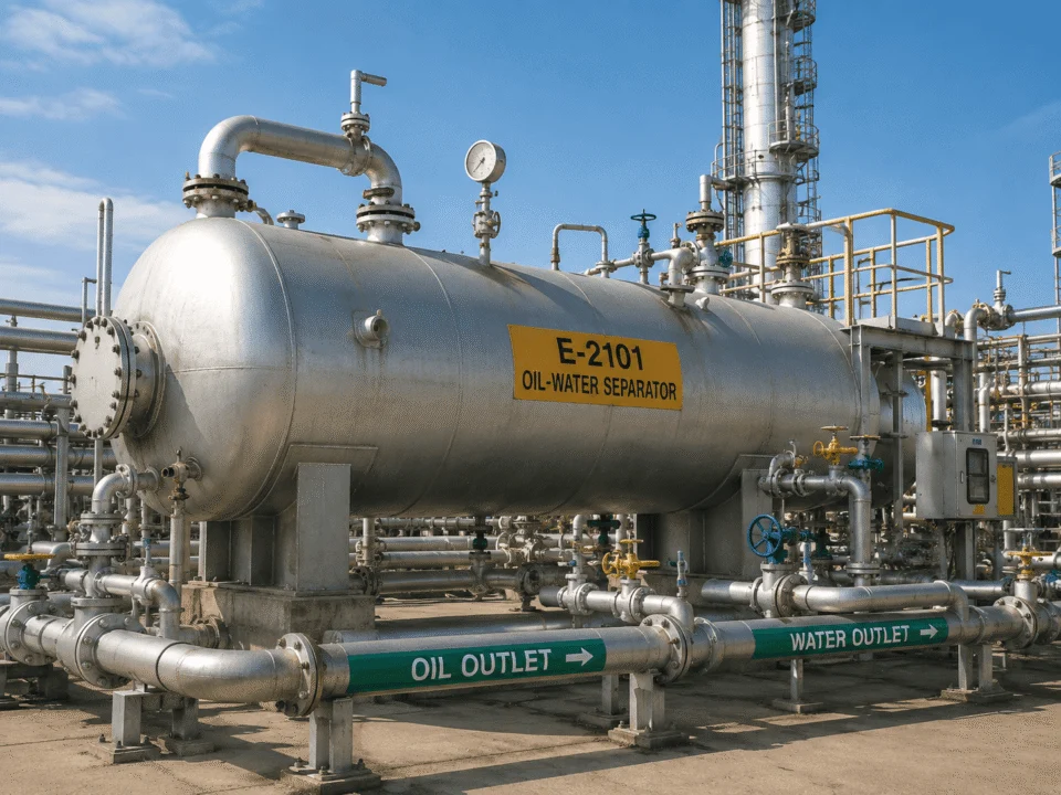
Oil-water separator manufactured by ChannelVessel
Oily Water 02

Oil-Water Separators

For oily wastewater, produced water, refinery wastewater, and industrial drainage.

Oil-water separators separate free oil from water using gravity settling, coalescing plates, and controlled flow distribution.

Separation performance depends on inlet oil concentration, oil droplet size, water temperature, specific gravity difference, retention time, and plate pack design.

Key Parameters
  • CPI design can support outlet oil content around 10–15 ppm under suitable inlet conditions.
  • API 421 reference droplet size often uses 150 μm for gravity separator design.
  • Capacities up to 500 m³/h depending on oil content and outlet target.
Learn More

Suitable for free oil separation before further treatment.

Filter vessel manufactured by ChannelVessel
Particle Filtration 03

Filter Vessels

For solid particle removal from liquid or gas streams.

Filter vessels use bags, cartridges, or other filter elements to remove solid particles from liquid or gas streams.

Bag filter housings are often used for moderate solid loading and simple replacement. Cartridge filter housings are commonly used for finer filtration, larger filter area, or more stable outlet quality.

Key Parameters
  • Filtration ratings from 1–200 μm depending on filter element selection.
  • Flow capacity up to 800 m³/h depending on viscosity, pressure drop, and filter area.
  • Single-bag, multi-bag, cartridge, and quick-open closure designs available.
Learn More

Used where element access and replacement cost matter.

Custom separation system manufactured by ChannelVessel
Custom Engineered 04

Custom Separation Systems

For mixed phases, special media, or process conditions that standard vessels cannot cover.

Custom separation systems combine vessel design, separation internals, piping, valves, instruments, controls, and skid-mounted packages around your process data.

Typical examples include three-phase separators, gas/oil/water packages, multi-stage filtration packages, separator + filter combinations, and special service equipment for high pressure, corrosive media, sour service, or limited installation space.

Key Parameters
  • Three-phase oil/gas/water separation available.
  • Pilot testing or process verification available when required.
  • ASME and PED certification options available for export projects.
Learn More

Built around process data, outlet target, and installation limits.

Not sure which product family fits your process?

Start with the medium, flow rate, pressure, contaminant type, and outlet quality target. Our engineering team can help narrow the direction before detailed quotation.

Medium Flow Rate Pressure Contaminant Type Outlet Target
Quick Selection

Quick Comparison of Separator and Filter Vessel Types

Different separation duties require different vessel structures and internals. Use the comparison below to check the main equipment type before reviewing sizing, performance, and project requirements.

Start with the separation target. Wet gas, oily water, solid particles, and mixed phases usually require different vessel layouts, internals, and maintenance methods.
Product FamilySeparation TargetTypical PerformancePressure RangeTypical Industries
01 Gas-Liquid Separator
Liquid droplets from gas or vapor≥99% removal of droplets ≥3–5 μm with wire mesh demister under suitable conditionsFull vacuum to 10 MPa
Oil & gas Chemical Compressed air Petrochemical
02 Oil-Water Separator
Free oil from waterOutlet oil content around 10–15 ppm with CPI design under suitable inlet conditionsAtmospheric to pressure-rated design
Water treatment Refinery Produced water Industrial wastewater
03 Filter Vessel
Solid particles from liquid or gas1–200 μm filtration rating depending on bag or cartridge selectionFull vacuum to 10 MPa
Chemical Water treatment Food process Utilities
04 Custom Separation System
Gas, oil, water, solids, or mixed contaminantsDesigned according to process data, outlet quality target, and operating dutyProject-specific, up to 10 MPa standard scope
Oil & gas Chemical Energy Modular process systems
01

Gas-Liquid Separator

Separation Target

Liquid droplets from gas or vapor

Typical Performance

≥99% removal of droplets ≥3–5 μm with wire mesh demister under suitable conditions

Pressure Range

Full vacuum to 10 MPa

Typical Industries

Oil & gas, chemical, compressed air, petrochemical

02

Oil-Water Separator

Separation Target

Free oil from water

Typical Performance

Outlet oil content around 10–15 ppm with CPI design under suitable inlet conditions

Pressure Range

Atmospheric to pressure-rated design

Typical Industries

Water treatment, refinery, produced water, industrial wastewater

03

Filter Vessel

Separation Target

Solid particles from liquid or gas

Typical Performance

1–200 μm filtration rating depending on bag or cartridge selection

Pressure Range

Full vacuum to 10 MPa

Typical Industries

Chemical, water treatment, food process, utilities

04

Custom Separation System

Separation Target

Gas, oil, water, solids, or mixed contaminants

Typical Performance

Designed according to process data, outlet quality target, and operating duty

Pressure Range

Project-specific, up to 10 MPa standard scope

Typical Industries

Oil & gas, chemical, energy, modular process systems

Selection Guide

How to Choose the Right Separator or Filter Vessel

The right separator or filter vessel depends on the phase or contaminant you need to remove, the required outlet quality, flow rate, operating pressure, temperature, and the maintenance method your plant can accept.

Many RFQs begin with a general phrase such as “separator vessel” or “filter housing,” but the correct solution depends on what is being separated and how clean the outlet stream must be.

What Are You Separating?

Choose by duty first
01 Duty
Separation Target

Liquid Droplets from Gas

Recommended Equipment Gas-liquid separator with mesh pad, vane pack, or baffle
Typical Target

≥99% removal of droplets ≥3–5 μm with mesh pad under suitable operating conditions.

02 Duty
Separation Target

Oil from Water

Recommended Equipment Oil-water separator with API or CPI configuration
Typical Target

Outlet oil content around 10–15 ppm with CPI design when inlet conditions are suitable.

03 Duty
Separation Target

Solids from Liquid

Recommended Equipment Filter vessel with bag or cartridge elements
Typical Target

1–200 μm filtration rating depending on element type and process requirement.

04 Duty
Separation Target

Gas + Oil + Water

Recommended Equipment Custom separation system or three-phase separator
Typical Target

Designed by gas flow, liquid loading, interface control, residence time, and outlet targets.

05 Duty
Separation Target

Mist or Aerosol Below 3 μm

Recommended Equipment Special custom separation system with fine coalescing or fiber-bed design
Typical Target

Project-specific design after confirming aerosol size, pressure drop, and maintenance limits.

Why Correct Selection Matters

Wrong selection can become operating cost.

Undersizing, over-filtering, or giving the separator too little residence time may look acceptable on a drawing, but it can create carryover, fast element blockage, or unstable outlet quality in operation.

!
Liquid carryover risk An undersized gas-liquid separator may send liquid into compressors, burners, heat exchangers, or downstream process equipment.
!
Fast filter blockage An unnecessarily fine filtration rating can block bags or cartridges too quickly and increase replacement cost.
!
Outlet target not reached An oil-water separator with too little residence time may not reach the outlet oil target even when the vessel is fabricated correctly.
Separation Principles

Separation Principles and Typical Performance

Separator performance is controlled by the separation mechanism, droplet or particle size, gas or liquid velocity, residence time, internal design, and allowable pressure drop.

Performance is process-dependent. Removal efficiency should be reviewed together with medium data, flow rate, liquid loading, pressure drop, and the selected internal structure.

Basic Separation Mechanisms

How separation happens

Gravity Settling

The vessel slows the stream so heavier droplets or solids can fall, or lighter oil droplets can rise.

Coalescence

Small droplets touch each other and merge into larger droplets that separate more easily.

Centrifugal Separation

Rotating flow pushes heavier droplets toward the vessel wall before they drain or collect.

Filtration Media

Bags or cartridges physically capture particles as the stream passes through the vessel.

Typical Mechanisms and Performance Ranges

Reference values depend on operating conditions
01

Gravity Settling

Typical Separable Size Liquid droplets ≥100 μm
Typical Performance Basic separation level
Plain Explanation

The vessel slows the flow so heavy droplets can fall or oil droplets can rise before the outlet.

02

Vane Pack / Baffle

Typical Separable Size Droplets ≥10–20 μm
Typical Performance 96–98% removal under suitable design conditions
Plain Explanation

The flow changes direction several times, and droplets hit the plates instead of following the gas path.

03

Wire Mesh Demister

Typical Separable Size Droplets ≥3–5 μm
Typical Performance ≥99% removal under suitable gas velocity and liquid loading
Plain Explanation

Fine droplets collide with wire mesh, combine into larger drops, and drain back into the vessel.

04

Cyclonic Separation

Typical Separable Size Droplets ≥8–10 μm
Typical Performance Suitable for high gas flow and compact layouts
Plain Explanation

The inlet creates a rotating flow, and heavier droplets move outward by centrifugal force.

05

Coalescing Plate / CPI

Typical Separable Size Oil droplets ≥60 μm
Typical Performance Outlet oil content around 10–15 ppm under suitable inlet conditions
Plain Explanation

Inclined plates shorten the distance oil droplets must travel before they rise and collect.

06

Bag / Cartridge Filtration

Typical Separable Size Solid particles 1–200 μm
Typical Performance Rated filtration accuracy according to selected element
Plain Explanation

Particles are trapped by filter media while the cleaned stream passes through the vessel outlet.

∑

Engineering Calculation Note

For gas-liquid separator sizing, vessel diameter is often checked with the Souders-Brown equation. For mesh-pad units, a common K-factor reference range is 0.07–0.11 m/s, but the final value depends on pressure, density, liquid loading, foaming tendency, and the selected demister type.

Technical Scope

General Technical Specifications

Our separators and filter vessels can be customized by pressure, temperature, diameter, material, internal structure, inspection level, and export certification requirement.

Custom-built, not shelf-only. Final design is reviewed according to process duty, code requirement, and outlet quality target.

Design Pressure

Full vacuum to 10 MPa; higher pressure can be reviewed by project.

Full vacuum Up to 10 MPa

Design Temperature

-45°C to 400°C depending on material, gasket, internal design, and code requirement.

Vessel Diameter

300–4,000 mm standard manufacturing range.

Materials

SA-516-70 carbon steel, SA-240 304/316L stainless steel, 2205 duplex stainless steel, lined carbon steel.

Design Codes

ASME Section VIII Div. 1 with U-Stamp, PED 2014/68/EU, GB150.

ASME PED GB150

Inspection

RT 100% or spot RT, UT, PT, hydrostatic test at 1.3 × MAWP, helium leak test optional.

Internals

Wire mesh demister, vane pack, baffle, CPI plate pack, filter bag, cartridge element, vortex breaker, distributor.

Demister Vane pack CPI plates Bags Cartridges Distributor

Closure Options

Bolted cover, davit-assisted cover, quick-open closure where permitted by design code.

Surface Treatment

Sandblasting and painting, pickling and passivation, polishing, internal lining, insulation support.

Typical Lead Time

6–12 weeks depending on vessel size, material, internals, inspection, and documentation scope.

6–12 weeks Size dependent Documentation scope

Need a condition outside this range?

Send your pressure, temperature, flow rate, material, outlet requirement, and drawings. We can review whether a custom separation system, special material, or different vessel layout is more suitable.

Request Engineering Review
Industry Applications

Applications by Industry

Separators and filter vessels are used in industrial plants where gas, liquid, oil, water, or solids must be controlled before the next process step.
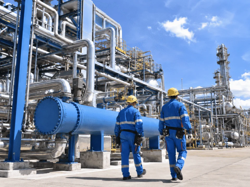
Different industries, different duties. Equipment structure, material, internals, and outlet quality target should be matched to the medium and operating condition of each process line.
Oil and gas separator application

Oil & Gas Industry

01

Oil & gas projects often use gas-liquid separators at wellheads, compressor inlets, gas gathering stations, and produced water treatment lines. For sour service or three-phase oil/gas/water duties, material and control requirements can be reviewed according to the project specification.

Wet Gas Produced Water Three-Phase Duty
Typical Application Focus
  • Gas-liquid separation before compressors or pipelines.
  • Custom systems with level control, interface control, and mist elimination.
Chemical industry separator application

Chemical Industry

02

Chemical plants use separators to remove mist from reactor off-gas, recover solvent droplets, protect vacuum pumps, and stabilize vapor or liquid streams before downstream equipment. For corrosive media, material selection can be reviewed by temperature, chloride level, pH, and cleaning conditions.

Mist Removal Solvent Recovery Corrosive Media
Typical Application Focus
  • Protection of vacuum pumps and downstream process equipment.
  • 316L, duplex, or lined carbon steel review for corrosive service.
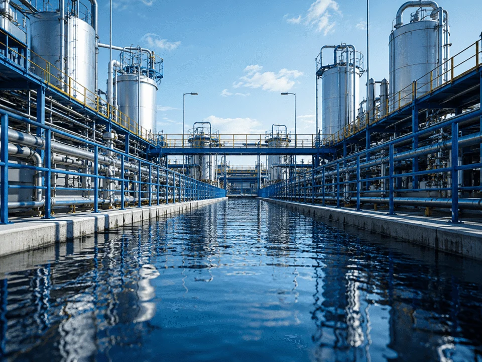
Water treatment separator and filter vessel application

Water Treatment

03

Water treatment systems often require oil-water separators, filter vessels, and multi-stage separation before discharge, reuse, or further treatment. CPI plate packs can improve oil droplet rise efficiency, while bag and cartridge housings are used for pre-filtration or polishing duties.

Oily Wastewater CPI Plates Filtration
Typical Application Focus
  • Oil-water separation before reuse, discharge, or downstream treatment.
  • Bag and cartridge vessels for suspended solids control.
Compressed air and utility system application

Compressed Air & Utility Systems

04

Compressed air systems need moisture and oil control after air receivers, dryers, or compressor discharge lines. A gas-liquid separator or filter vessel can remove condensed water, oil mist, or particles before instruments, pneumatic tools, or process users.

Moisture Control Oil Mist Utility Lines
Typical Application Focus
  • Stable drainage, demister selection, and pressure drop control.
  • Protection for instruments, pneumatic tools, and user points.
Food and beverage filter vessel application

Food & Beverage Industry

05

Food and beverage process lines may require stainless steel filter vessels, cleanable internals, polished surfaces, and gasket materials suitable for the medium. Sanitary-style details should be confirmed by cleaning method, surface finish, viscosity, and product contact requirements.

Stainless Steel Cleanable Design Polished Surface
Typical Application Focus
  • Filter vessels for clean process lines and product-contact review.
  • Gasket, finish, and cleaning requirements checked case by case.
Workshop & Quality Control

Manufactured and Tested in Our Pressure Vessel Workshop

Our manufacturing process includes material cutting, plate rolling, welding, nozzle fitting, internal support fabrication, internal component installation, non-destructive examination, hydrostatic testing, internal re-inspection, surface treatment, packaging, and shipment preparation.
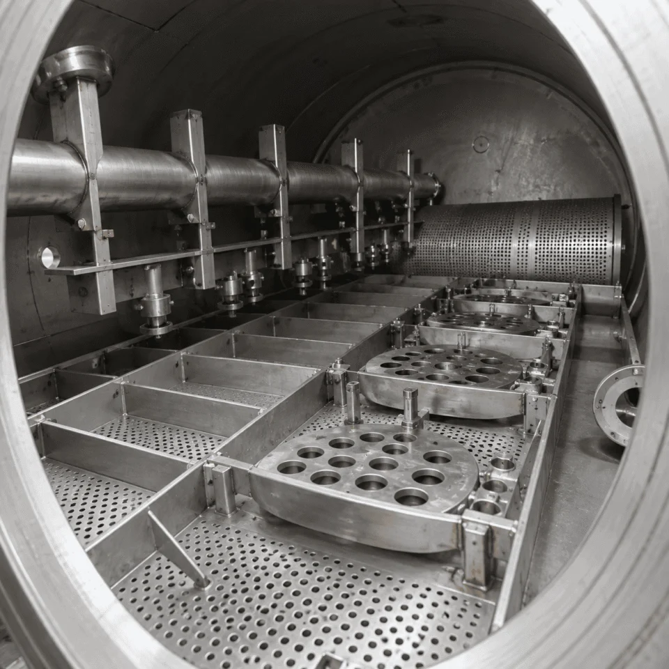
The performance of a separator or filter vessel depends not only on shell strength, but also on the installation accuracy of the internal separation parts.
Separator and filter vessel manufacturing in ChannelVessel workshop
Built around the internals. Demister, CPI plates, baffles, distributors and filter elements are checked against drawings before closure.

Manufacturing Process

Each separator or filter vessel is fabricated through controlled workshop steps, from raw material preparation to final inspection and shipment packaging.

Workshop workflow
01

Material Preparation

Cutting, plate rolling and material traceability review before fabrication starts.

02

Shell Fabrication

Welding, nozzle fitting, supports and main vessel assembly are completed to drawing.

03

Internal Support Fabrication

Supports, frames, distributors and mounting parts are fabricated for the selected internals.

04

Internal Component Installation

Demister pads, vane packs, CPI plates, baffles, filter bags or cartridges are installed.

05

Inspection & Testing

NDE, dimensional checking, hydrostatic testing and internal re-inspection are arranged.

06

Surface Treatment & Shipment

Painting, passivation, lining, packaging and export shipment preparation are completed.

Internal Accuracy

Internal Parts Are Not Decorative Parts

For separation equipment, the internals directly affect droplet capture, oil-water separation, pressure drop, drainage behavior, and maintenance access.

Wire Mesh Demister Fit Demister pads are fitted tightly to reduce gas bypass around the pad.
CPI Plate Spacing Plate spacing is checked against drawing tolerance, typically within ±2 mm for standard plate-pack assembly.
Distributor / Tray Levelness Tray or distributor horizontality is checked before final closure where applicable.
Maintenance Access Internal layout is reviewed for cleaning, replacement and inspection access.

Inspection and Documentation Options

Inspection options can be matched to project specifications, certification requirements, and export documentation needs.

RT UT PT Hydrostatic Test Dimensional Checking Material Traceability Pressure Test Records Welding Records Export Documentation ASME U-Stamp PED Documentation

Certified Project Support

For certified projects, we can manufacture according to ASME Section VIII Div. 1 with U-Stamp and provide PED-related documentation when required.

View Quality & Certifications
01 What is the difference between a separator and a filter vessel?

A separator removes phases by gravity, coalescence, centrifugal force, or internal flow control, while a filter vessel removes particles through filter media. A gas-liquid separator separates liquid droplets from gas. An oil-water separator separates oil from water. A filter vessel uses bags or cartridges to capture solids or fine contaminants.

02 What droplet size can a gas-liquid separator remove?

A gas-liquid separator with a wire mesh demister can typically remove droplets ≥3–5 μm at ≥99% efficiency under suitable gas velocity and liquid loading. A vane pack or baffle design is normally used for larger droplets, often ≥10–20 μm, with typical removal efficiency around 96–98% under suitable conditions.

03 How do I size a separator vessel?

A separator vessel is sized by flow rate, pressure, temperature, gas and liquid density, liquid loading, droplet size target, allowable pressure drop, and required residence time. For gas-liquid separators, vessel diameter is commonly checked with the Souders-Brown equation. Send us your process data and we can review the required diameter, length, nozzles, and internals.

04 Can you design to API 421 or NACE MR0175?

Yes, we can review API 421 oil-water separator requirements and NACE MR0175 sour service requirements when they are specified in your project documents. For API 421-style oil-water separation, we check flow rate, oil droplet size, specific gravity difference, temperature, and outlet oil target. For NACE service, material selection and welding requirements must be confirmed before fabrication.

05 What information do you need for a quotation?

For a quotation, we need flow rate, operating pressure, operating temperature, medium composition, and required separation target. If available, please also send inlet contaminant concentration, outlet quality requirement, droplet or particle size, material preference, design code, nozzle orientation, installation space, and any drawing or datasheet from your engineering team.

06 What is the typical lead time and can you ship worldwide?

The typical lead time for separators and filter vessels is 6–12 weeks depending on vessel size, material, internals, certification, inspection, and documentation. We can prepare export packaging and support worldwide shipment by sea, truck, or multimodal transport according to project location and delivery terms.

Scroll to Top
DRAWING & FILE REVIEW

Send Your Drawings

Upload your drawings, datasheets or existing specifications. Our engineering team will review the files and respond with technical feedback.

Engineering Review

Drawings, specifications and process requirements

Confidential File Handling

Project files are used only for technical review and quotation

Faster Technical Feedback

Clearer inputs help us respond more accurately and efficiently

DRAWING & FILE REVIEW

Send Your Drawings

Upload your drawings, datasheets or specifications. Our engineering team will review your files and provide technical feedback.

Contact Form Demo (#3)
Project Protected NDA available
12h Response
ASME / PED
AFTER SUBMISSION
01 Review
→
02 Confirm
→
03 Quote
TECHNICAL QUOTATION

Get a
Technical Quote

Tell us what you need. Our engineering team will review your requirements and respond within 12 hours.

Engineered for Your Application

From concept to certified manufacturing

Global Compliance

ASME, PED and other international standards

Expert Support

Direct access to our engineering team

TECHNICAL QUOTATION

Get a Technical Quote

Tell us what you need. Our engineering team will review your requirements and respond within 12 hours.

Contact Form Demo
Project Protected NDA available
12h Response
ASME / PED
AFTER SUBMISSION
01 Review
→
02 Confirm
→
03 Quote