
ChannelVessel Intelligent Equipment Co., Ltd. Contact Us
Industrial Oily Wastewater Separation

Industrial Oil Water Separators for Oily Wastewater Treatment

Custom-engineered oil water separators for removing free and separable hydrocarbons from industrial wastewater before downstream treatment, discharge or reuse.

ChannelVessel designs gravity, CPI, coalescing and project-specific oil water separation systems around the actual wastewater conditions—not simply around a nominal flow rate.

Typical Single-System Range 1–300 m³/h
Construction Options Carbon Steel / SS304 / SS316L
Available Configurations Gravity / CPI / Coalescing / Pressurized Separation
Engineering Basis Flow, Oil Density, Droplet Size, Temperature, Solids & Outlet Target

Larger duties can be evaluated using larger custom separators or parallel treatment trains according to the project hydraulic load.
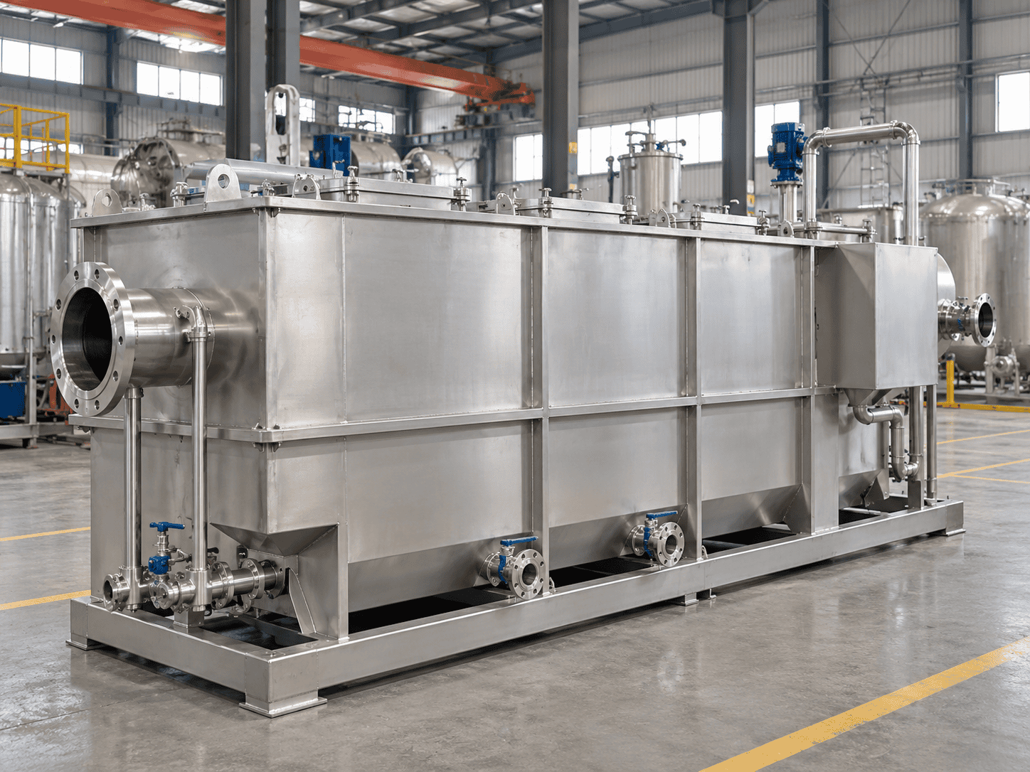
Industrial oil water separator for oily wastewater treatment
Custom Industrial Separator
Separation Boundary

Start With the Oil Condition, Not the Separator Size

An oil water separator should not be selected only by flow rate. The first engineering question is more fundamental: what form is the oil actually in? Free oil, dispersed droplets, stable emulsions and dissolved hydrocarbons behave very differently inside a separator.

Best Fit for Gravity Separation
Enhanced Physical Separation
Usually Needs Additional Treatment
Not a Gravity-Separation Duty

Free Oil

Best Fit

Free oil exists as droplets large enough to rise naturally because its density is lower than the surrounding water. This is the most suitable duty for conventional gravity separation.

Typical Approach Gravity separation with sufficient calm area, oil collection and sludge management.

Dispersed Oil

Enhanced

Smaller droplets can remain dispersed through the wastewater while still being physically separable. As droplet size decreases, rise velocity drops sharply.

Typical Approach CPI, inclined plates or coalescing media can improve separation for suitable droplets.

Emulsified Oil

Treatment

Pumps, mechanical shear, detergents and surfactants can stabilize very small oil droplets and prevent them from coalescing. A larger separator alone may not solve the problem.

Typical Approach Evaluate demulsification, chemical conditioning, DAF or another treatment stage.

Dissolved Hydrocarbons

Beyond OWS

Dissolved hydrocarbons do not exist as separate floating droplets, so increasing gravity-separator size does not make them rise to the surface.

Typical Approach Adsorption, advanced filtration, biological treatment or another polishing process may be required.
Practical Selection Rule
Free oil is mainly a separation problem. Stable emulsion is usually a treatment problem.

Before sizing the equipment, confirm whether the target contaminant can actually separate by density. This avoids one of the most common purchasing mistakes: buying a larger separator for wastewater that does not respond to gravity separation.

When the Oil Condition Is Uncertain

A settling test, laboratory characterization or pilot test can be more useful than immediately selecting a larger separator. A poor gravity-separation result may indicate that the wastewater needs conditioning or a different treatment technology.

Working Principle

How an Industrial Oil Water Separator Works

Effective oil water separation depends on creating a controlled hydraulic environment where turbulence is reduced and oil, water and solids are given enough opportunity to move according to their density and droplet behavior.
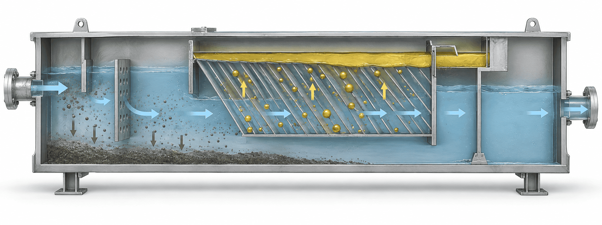
Oil water separator working principle cutaway showing solids settling, oil droplet rise, coalescing plates and treated water outlet
Oil Water Separation Process
Flow Calming

An inlet chamber, diffuser or baffle reduces inlet momentum and distributes wastewater more evenly across the separator.

Solids Settling

Dense grit and suspended solids move downward into a settling zone, sludge area or hopper where provided.

Oil Droplet Rise

Oil droplets lighter than water move upward. Rise velocity depends strongly on droplet size, density difference and viscosity.

Droplet Coalescence

CPI plates or coalescing media help suitable small droplets combine into larger droplets that separate more easily.

Oil Collection

Separated hydrocarbons accumulate above the water phase and are removed through a skimmer, weir or collection chamber.

Treated-Water Outlet

The water phase exits below the oil layer while collected oil remains inside the separator for controlled removal.

Why Inlet Hydraulics Matter

A separator can have enough nominal volume and still perform poorly if the inlet creates excessive turbulence, short-circuiting or uneven flow distribution.

Good separator design therefore controls how wastewater enters the vessel before relying on residence time, plate area or coalescing media to perform the separation.

Design Basis

Why Two Separators With the Same Flow Rate Can Need Completely Different Sizes

A flow rate such as 20 m³/h is not enough information to size an oil water separator. Two wastewater streams can have the same flow but require very different separator areas because hydraulic loading is only one part of the separation problem.

Stokes-Type Relationship
Rise velocity ∝ density difference × droplet diameter² ÷ viscosity

For small spherical droplets under ideal laminar conditions, droplet diameter has a squared effect on theoretical rise velocity. That is why a small change in design droplet size can have a major effect on separator area.

Relative Oil-Droplet Rise Velocity

Same oil density, water density, temperature, viscosity and laminar Stokes-law conditions.
50 μm
1×
75 μm
2.25×
100 μm
4×
150 μm
9×

Maximum Flow Rate

Peak flow determines hydraulic loading and may control the required separator area more than average flow.

Oil Droplet Size

Smaller droplets rise more slowly and may require lower loading, more area or enhanced coalescence.

Oil Specific Gravity

As oil density approaches water density, the buoyant driving force becomes smaller and separation becomes harder.

Wastewater Temperature

Lower temperature commonly increases viscosity and reduces oil-droplet rise velocity.

Water Viscosity

Higher viscosity increases resistance to droplet movement and slows physical separation.

Inlet Oil Concentration

Oil loading affects the collection chamber, skimming arrangement and removal frequency.

Suspended Solids

Solids accumulate as sludge, reduce effective volume and can foul CPI or coalescing passages.

Surfactants & Detergents

These chemicals can stabilize emulsions and prevent droplets from coalescing normally.

Hydraulic Surges

Sudden flow increases reduce separation time and may carry previously separated oil downstream.

Required Outlet Quality

The target determines whether primary separation is sufficient or whether downstream polishing is required.

Flow rate is only one part of the design basis.

A separator selected only from a catalogue flow rating may be too small for difficult wastewater—or unnecessarily large for an easier duty. Hydraulic conditions and wastewater properties should be evaluated together.

View Selection Guides
Typical Customization Range

Oil Water Separators Engineered Around the Process

As a custom oil water separator manufacturer, ChannelVessel can configure the equipment around the separation mechanism, installation conditions, corrosion environment, maintenance strategy and required operating philosophy. The values below represent a typical engineering and manufacturing range rather than one fixed catalogue specification.

Design Item
Typical Customization
Flow Capacity
Typical single-system range 1–300 m³/h; larger duties evaluated separately.
Separator Type
Gravity / CPI / Parallel Plate / Coalescing / Pressurized Separation
Construction Material
Carbon Steel / SS304 / SS316L
Installation
Above-ground / Skid-mounted / Integrated treatment package
Feed
Gravity-fed or pumped
Oil Handling
Overflow weir / Skimmer / Oil collection chamber
Solids Handling
Settling zone / Sludge hopper / Drain connections
Plate Pack
CPI / Inclined parallel plates / Removable coalescing media
Controls
Manual / Semi-automatic / PLC-based
Instrumentation
Level / Interface / Flow / Pressure options
Electrical
Standard or hazardous-area options according to project classification
Surface Protection
External coating / Internal coating or lining where required
Connections
Flanged and project-specific nozzle configuration
Design Pressure
Determined by separator technology and operating conditions
Documentation
Drawings, material documents, inspection records and project documentation as specified
System Arrangement

Larger Flow Does Not Always Mean One Larger Vessel

High-flow duties can sometimes be handled more effectively using parallel separator trains, improving transport, maintenance isolation, phased capacity expansion and operating flexibility.

Pressure Basis

Atmospheric and Pressurized Duties Are Not the Same

API-type and CPI separators commonly operate at atmospheric or low pressure, while hydrocyclone or vessel-type systems require a different mechanical and hydraulic design basis.

Engineering Reference Data

API-Type Gravity Separator Design References

API Publication 421 has historically been one of the best-known engineering references for refinery gravity separators. Its methodology remains useful for understanding droplet rise, hydraulic velocity and separator geometry, but reference values should not be treated as universal ChannelVessel product specifications.

Design Item
Reference Value
Reference Oil Droplet Diameter
Approximately 150 μm for conventional refinery-separator methodology.
Maximum Horizontal Velocity
≤3 ft/min or ≤15 × droplet rise velocity, whichever is lower.
Typical Separation Depth
Approximately 3–8 ft.
Typical Channel Width
Approximately 6–20 ft.
Depth-to-Width Ratio
0.3–0.5.
Length-to-Width Ratio
≥5.
Important Sizing Inputs
Flow, minimum wastewater temperature, water specific gravity, viscosity, oil specific gravity and design droplet diameter.
Current Status
API Publication 421 is a withdrawn publication.

Its design methodology can still be referenced as an engineering basis, but it should not be presented as a current standalone certification or universal compliance claim.

Reference Data ≠ Product Guarantee

A conventional API-style separator, a compact CPI unit and a pressurized separation vessel do not use the same geometry or performance basis. Final design must follow the selected technology and actual project conditions.

Use the Methodology, Not Just the Label

A statement such as “API-type separator” does not prove that the equipment is correctly sized. A meaningful design basis should identify the wastewater properties, design droplet size and hydraulic conditions that the separator is intended to handle.

For current projects, purchaser specifications, applicable local requirements and any required pressure-equipment codes should take precedence over generic historical reference values.

Technology Selection

Gravity vs CPI vs Coalescing vs Hydrocyclone

There is no single separator configuration that is best for every oily wastewater stream. The correct choice depends on droplet size, solids loading, footprint, pressure condition, maintenance expectations and outlet target.
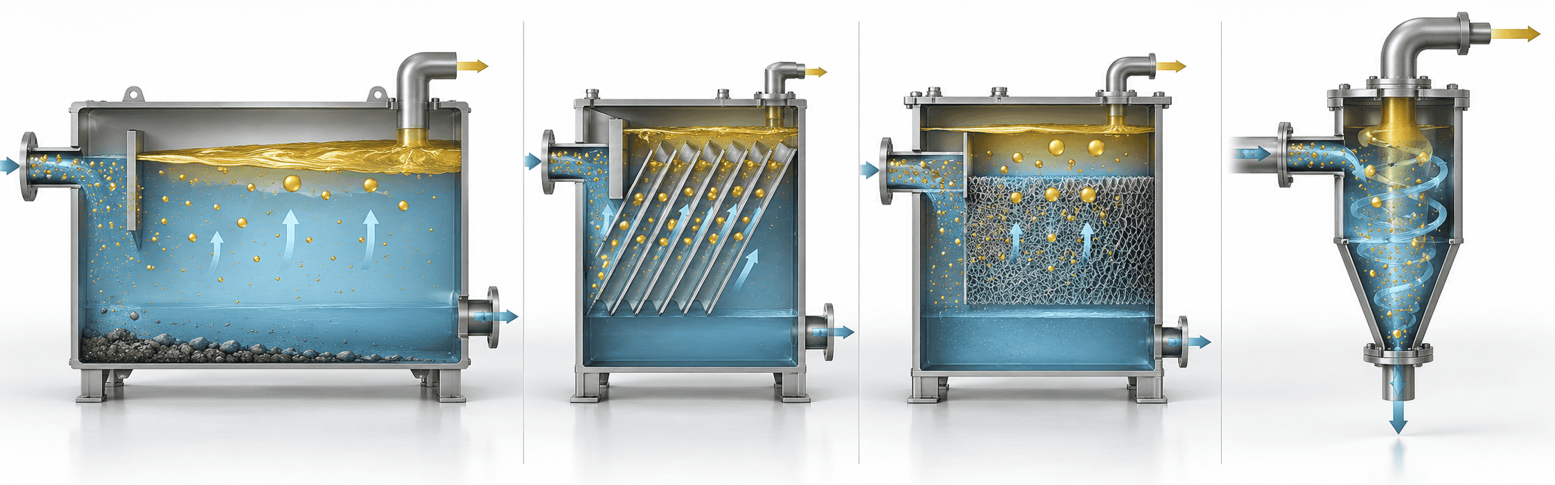
Comparison of gravity, CPI, coalescing and hydrocyclone oil water separation technologies
Four Separation Approaches
Technology
Best Suited For
Main Advantage
Main Limitation
Conventional Gravity Simple & Accessible
Larger free-oil droplets and applications where sufficient footprint is available.
Low energy demand, simple internals and relatively good tolerance of solids.
Requires more footprint and is less effective as droplet size becomes smaller.
CPI / Parallel Plate Compact Gravity
Free and dispersed oil where reducing separator footprint is important.
Increases effective separation area and shortens droplet travel distance.
Plate channels can foul when solids loading and sludge management are not controlled.
Coalescing Media Smaller Droplets
Smaller dispersed droplets that are still physically capable of coalescing.
Promotes formation of larger droplets and can improve compact separation.
Stable emulsions and heavy solids can reduce effectiveness and increase fouling.
Hydrocyclone / Pressurized Pressurized Duty
Pressurized process streams and compact high-throughput separation duties.
Compact arrangement and suitable for certain oilfield and process applications.
Performance depends strongly on pressure, fluid properties and operating range.

Quick Selection Cues

Choose conventional gravity when simplicity, access and solids tolerance matter more than footprint.
Choose CPI when free oil is separable but installation space is limited.
Consider coalescing media when droplets are smaller but still capable of combining.
Consider hydrocyclone or pressurized separation only when the process conditions support that technology.
Solids & Sludge Management

Oil Is the Target. Solids Are Often the Maintenance Problem.

A separator can be hydraulically large enough on paper and still perform poorly after months of operation if sludge accumulation and plate fouling were ignored during design. Solids management directly affects long-term separation performance.

Solids Enter

Sand, scale, corrosion products, metal fines and other suspended material enter with the oily wastewater.

Sludge Accumulates

Heavier particles settle and gradually occupy the lower separation volume.

Plate Passages Foul

CPI or coalescing channels begin to narrow when solids and sticky deposits build up.

Flow Area Decreases

Less available passage area forces the same flow through a smaller hydraulic section.

Velocity Increases

Higher local velocity reduces effective separation time and can disturb previously separated oil.

Oil Carryover Rises

Performance deteriorates even though the original separator size has not changed.

High-Solids Wastewater Needs a Different Internal Layout

Enlarged primary settling zones
Upstream grit or solids removal
Sludge hoppers or dedicated sludge zones
Drain and flushing connections
Removable CPI or coalescing plate packs
Wider plate spacing where fouling risk is high
Adequate maintenance clearance above the media
Realistic access for inspection and cleaning
Engineering Data Sheet

What We Need to Size and Accept Your Separator

A reliable proposal starts with the process data. The more accurately the wastewater is characterized, the less the equipment must rely on assumptions. The same principle applies to acceptance testing: define how performance will be measured before fabrication.

Flow Conditions
Required
Normal Flow RateContinuous or typical operating flow.
Maximum Design FlowHighest sustained hydraulic design case.
Peak / Surge FlowIntermittent batch, storm or process surge conditions.
Operating PatternContinuous, batch, intermittent or variable duty.
Oil Phase
Required
Oil / Hydrocarbon TypeProduct family or process contaminant.
Oil Specific GravityDensity difference strongly affects rise velocity.
Inlet Oil ConcentrationExpected normal and maximum loading.
Oil ConditionFree, dispersed, emulsified or uncertain.
Droplet SizeProvide measured or assumed design value if known.
Emulsion RiskNote detergents, surfactants or high-shear pumps.
Water & Solids
Required
Minimum TemperatureImportant for viscosity and winter sizing.
Normal TemperatureTypical operating water temperature.
pH / ChloridesImportant for material selection and corrosion.
Chemicals / SurfactantsMay change oil separation behavior.
Suspended SolidsConcentration and expected solids loading.
Solids CharacterGritty, sticky, oily, settleable or fine suspended solids.
Project & Treatment Target
Helpful
Required Outlet Oil LevelTarget concentration or downstream requirement.
Downstream TreatmentDAF, filtration, biological treatment or reuse polishing.
Available FootprintSpace limits can influence technology selection.
PFD / P&IDExisting process drawings significantly improve proposal accuracy.
Hazardous AreaElectrical and instrumentation classification where applicable.
Code / Inspection ScopeMechanical code, documentation and inspection requirements.

Do Not Know Every Value?

That is common during early project development. Send the process data you already have, together with any wastewater analysis, laboratory report, PFD, P&ID or information about the existing separator.

ChannelVessel can identify which missing inputs materially affect technology selection and separator sizing before the design basis is finalized.

Performance Acceptance Basis

Do Not Specify Only “Outlet Oil ≤ XX ppm.”

A meaningful performance guarantee should define the operating condition and analytical basis used to determine whether the separator passed the test.

Operating Flow

Define whether acceptance is at normal, design or maximum hydraulic flow.

Influent Condition

Define inlet oil concentration and whether the oil is free, dispersed or otherwise conditioned.

Wastewater Temperature

State the test temperature or acceptable temperature range.

Sampling Location

Identify the exact upstream and downstream sample points.

Stabilization Period

Define how long the system must operate before performance samples are collected.

Sampling Frequency

State whether one sample or multiple samples over a defined period are required.

Analytical Parameter

Define oil & grease, non-polar material or another specified measurement basis.

Analytical Method

Agree the laboratory or regulatory test method before fabrication and commissioning.

Send the process conditions before asking for a final separator size.

The correct technology, internal configuration and equipment size should follow the wastewater data—not the other way around.

Send Your Process Data
Internal Configuration & Options

Internal Features Should Match the Wastewater

An oil water separator is more than an empty tank with one inlet and one outlet. The internal arrangement determines how flow enters, where solids collect, how droplets separate, how oil is removed and how the equipment will be maintained after installation.
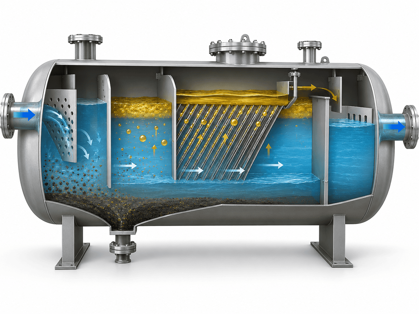
Oil water separator internal configuration cutaway showing inlet distribution, CPI coalescing media, oil collection, sludge zone and treated water outlet
Separator Internal Configuration

Inlet Distribution

A diffuser, calming chamber or inlet baffle reduces inlet momentum and helps distribute wastewater across the separator.

Primary Separation Zone

Provides the hydraulic volume and surface area required for bulk gravity separation before enhanced stages.

CPI / Coalescing Plate Pack

Inclined or corrugated media can increase effective separation area and promote coalescence where appropriate.

Oil Collection System

Separated hydrocarbons can be removed through an adjustable overflow, skimmer, trough or dedicated collection chamber.

Sludge Collection

Settled solids are retained in a lower zone, hopper or dedicated sludge compartment according to solids loading.

Outlet Chamber

The outlet arrangement keeps floating oil inside the separator while maintaining the intended operating liquid level.

Verification

Sampling Connections

Upstream and downstream sample points can be incorporated for commissioning, performance verification and project acceptance testing.

Hydrocarbon Service

Vapor & Odor Control

Covers, vent connections and project-specific vapor-control provisions can be incorporated where required by the site or process.

Future Modification

Retrofit Access

Internal layouts can allow future removal or replacement of plate packs, coalescing modules, skimmers or other internals.

Automation

Instrumentation Options

Interface detection, level alarms, flow indication, pressure indication, pump control and PLC integration can be added as required.

Maintainability Matters
A compact separator that cannot be cleaned efficiently is not a good compact design.

Covers, manways, plate-pack removal space, drains and maintenance clearance should be incorporated before fabrication rather than added as an afterthought after the equipment reaches site.

Materials & Construction

Select the Material From the Wastewater Chemistry

“Industrial wastewater” is not a material specification. The separator body, internals, seals and piping components should be selected from the actual corrosion environment, temperature and chemical exposure rather than from a generic equipment category.

Material Selection Principle
The wastewater chemistry should drive the material—not the other way around.

A separator handling neutral hydrocarbon-contaminated water can require a very different construction material from one exposed to chlorides, acids, alkalis, cleaning chemicals or aggressive process additives.

Carbon Steel Cost-Effective Base Option

Suitable for many compatible industrial services where corrosion can be controlled. Depending on the wastewater, the design may require internal coating, lining or corrosion allowance rather than bare carbon steel.

SS304 General Stainless Service

Commonly considered for general industrial wastewater where stainless construction is preferred and chloride exposure is moderate. Final suitability still depends on pH, temperature, chlorides and process chemicals.

SS316L Higher Corrosion Resistance

Provides improved corrosion resistance over 304 in many chloride-containing and chemically demanding services, but it should not be treated as universally immune to chloride attack or all chemical environments.

Coated / Lined Steel Barrier Protection

Useful where the structural and economic benefits of carbon steel are desired together with additional internal corrosion protection. Coating compatibility, surface preparation and inspection requirements should be defined in the project specification.

Project-Specific Alloy Special Chemistry

Where standard carbon steel or common stainless grades are unsuitable, a higher alloy or project-specific material can be evaluated from the actual process chemistry and corrosion mechanism.

Material Selection Inputs

What Changes the Corrosion Decision?

Wastewater pH
Chloride concentration
Operating temperature
Hydrocarbon composition
Dissolved process chemicals
Cleaning agents
Chemical dosing additives
Expected service life

The Vessel Shell Is Only Part of the Material Decision

Plate packs, seals, gaskets, internal supports, skimmer components, instruments and piping connections also contact the process fluid and must be compatible with the wastewater.

A corrosion-resistant shell with incompatible elastomers, plate media or internal hardware can still create reliability problems in service.

Treatment Train & Applications

An Oil Water Separator Is Often the First Stage, Not the Entire Treatment Plant

For many industrial wastewater systems, an oil water separator provides primary bulk removal of free and separable oil before more sensitive downstream treatment. The complete process should be selected from the final water-quality target—not by forcing one separator to solve every contaminant.
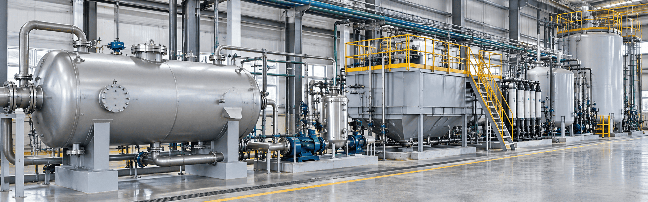
Industrial oily wastewater treatment system integrating oil water separation with downstream treatment equipment
Industrial Oily Wastewater Treatment
Collection / Equalization

Balances variable influent flow and provides a more stable feed condition for downstream separation.

Oil Water Separation

Removes bulk free and separable oil before it loads more sensitive treatment equipment.

Chemical Treatment / DAF

Can address fine dispersed oil, suspended solids or emulsified contaminants when required.

Filtration / Polishing

Reduces remaining solids or contaminants to meet downstream process or reuse requirements.

Biological / Reuse / Discharge

Final treatment depends on the wastewater chemistry and site-specific outlet requirement.

Why Primary Separation Matters

Removing bulk free oil upstream can reduce the oil load reaching DAF systems, filters, membranes and biological treatment equipment. That can improve downstream stability and reduce unnecessary loading on equipment intended for finer treatment duties.

At the same time, dissolved hydrocarbons and stable emulsions should not be treated as a gravity-separation problem simply because oil is present in the wastewater.

Specification Mistakes & FAQ

Before You Specify an Oil Water Separator

Many separator problems begin in the purchasing specification rather than in fabrication. The most reliable system is the one whose design basis, maintenance strategy and acceptance criteria match the actual wastewater.

Hydraulics

Sizing Only From Average Flow

Peak flow, batch discharge and stormwater surges can control the real hydraulic requirement even when the average flow appears modest.

Performance

Using “15 ppm” as a Universal Specification

A fixed outlet number does not describe the inlet oil condition, droplet size, solids loading, temperature or analytical test method.

Chemistry

Ignoring Emulsion Stability

A larger gravity separator cannot automatically solve stable emulsified oil. The wastewater may require conditioning or another treatment mechanism.

Internals

Using Tight Plate Spacing for High-Solids Water

More theoretical surface area adds little value if sludge rapidly blocks the passages and increases local hydraulic velocity.

Maintenance

Ignoring Sludge Storage and Cleaning Access

Drain points, manways, removable internals and maintenance clearance should be considered before the separator reaches site.

Acceptance

Writing an Outlet Guarantee Without a Test Method

Sampling location, flow, influent condition, stabilization period and analytical method should be agreed before commissioning.

Can an oil water separator remove emulsified oil?

A gravity separator is mainly intended for free and separable oil. Coalescing media can help smaller droplets that are still capable of combining, but a stable emulsion may require chemical conditioning, DAF or another treatment method.

What oil droplet size should the separator be designed for?

There is no universal value for every application. Conventional API-type refinery methodology has historically used approximately 150 μm as a reference condition, while enhanced systems may be designed around smaller droplets. The selected value should reflect the wastewater and required outlet condition.

Does wastewater temperature affect separator performance?

Yes. Lower wastewater temperature generally increases viscosity and reduces oil-droplet rise velocity. Seasonal minimum temperature can therefore be more important than the normal summer operating temperature.

Is CPI always better than conventional gravity separation?

No. CPI can reduce footprint, but narrower plate passages are more sensitive to sludge and fouling. Conventional gravity separation can be preferable where solids tolerance, simple access and maintainability are more important than minimum footprint.

What affects the price of an industrial oil water separator?

Main factors include flow capacity, separator technology, construction material, CPI or coalescing media, sludge handling, oil-removal system, instrumentation, hazardous-area requirements, coating or lining, pressure condition, inspection scope and documentation.

Can an existing oil water separator be upgraded instead of replaced?

Sometimes. Existing geometry, hydraulic loading, structural condition, solids loading and internal access can be evaluated for possible retrofit with CPI plates, coalescing media, improved inlet distribution, skimmers, sludge-removal modifications or instrumentation.

When should a laboratory or pilot test be considered?

Testing is useful where emulsion stability is uncertain, surfactants are present, oil chemistry is unusual, droplet-size distribution is unknown, wastewater varies significantly or the required outlet target is unusually stringent.

Is API 421 still a current standard?

API Publication 421 has been withdrawn. Its gravity-separator methodology remains widely referenced as an engineering basis, but it should not be represented as a current standalone certification. Current project specifications and applicable requirements should control the final design.

Can an oil water separator achieve 15 ppm oil in water?

It may be possible in some services, but it is not a universal performance value. The result depends on influent oil condition, droplet size, concentration, temperature, solids, hydraulic loading, sampling basis and whether downstream polishing is included.

What information do you need for a quotation?

At minimum, provide normal flow, maximum flow, wastewater temperature, oil type, oil specific gravity, inlet oil concentration, solids condition and required outlet oil level. PFDs, P&IDs, wastewater analysis reports and project specifications improve proposal accuracy.

Can ChannelVessel supply a complete separation package?

Yes. Where the project requires pumps, filtration, instruments, controls, solids removal or multiple separation stages, the equipment can be developed as a broader custom separation package instead of a standalone separator.

Final Engineering Step

Need an Oil Water Separator Sized for Your Actual Waste Stream?

Send the wastewater conditions, oil properties, solids information and required outlet target. ChannelVessel can use the process data to determine the appropriate separation technology, internal configuration, material, equipment size and acceptance basis.

Scroll to Top
DRAWING & FILE REVIEW

Send Your Drawings

Upload your drawings, datasheets or existing specifications. Our engineering team will review the files and respond with technical feedback.

Engineering Review

Drawings, specifications and process requirements

Confidential File Handling

Project files are used only for technical review and quotation

Faster Technical Feedback

Clearer inputs help us respond more accurately and efficiently

DRAWING & FILE REVIEW

Send Your Drawings

Upload your drawings, datasheets or specifications. Our engineering team will review your files and provide technical feedback.

Contact Form Demo (#3)
Project Protected NDA available
12h Response
ASME / PED
AFTER SUBMISSION
01 Review
→
02 Confirm
→
03 Quote
TECHNICAL QUOTATION

Get a
Technical Quote

Tell us what you need. Our engineering team will review your requirements and respond within 12 hours.

Engineered for Your Application

From concept to certified manufacturing

Global Compliance

ASME, PED and other international standards

Expert Support

Direct access to our engineering team

TECHNICAL QUOTATION

Get a Technical Quote

Tell us what you need. Our engineering team will review your requirements and respond within 12 hours.

Contact Form Demo
Project Protected NDA available
12h Response
ASME / PED
AFTER SUBMISSION
01 Review
→
02 Confirm
→
03 Quote