
Gas Liquid Separators Engineered Around Your Process Conditions
Separate entrained liquid from process gas with vertical or horizontal separator vessels engineered around actual gas flow, liquid loading, pressure, temperature, fluid properties, droplet size and downstream requirements.
Project-specific vessel layout for gas and liquid duty.
Configured around droplet size, capacity and fouling risk.
Flexible fabrication for plant installation requirements.
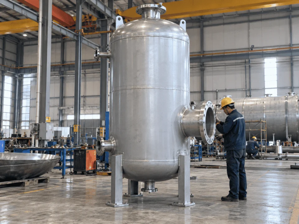
A Separator Must Do More Than Remove Liquid
Reliable gas–liquid separation depends on how the two-phase stream enters the vessel, how bulk liquid disengages, how the gas is stabilized, how fine droplets are captured and how collected liquid drains without being carried back into the outlet gas.
The inlet, disengagement zone, mist eliminator and liquid section have to work together as one process system.
Control Inlet Momentum
The inlet device reduces or redirects incoming momentum so high-velocity gas and liquid do not disturb the entire vessel.
Remove Bulk Liquid First
Large droplets and free liquid should disengage before the gas reaches the fine-separation section.
Stabilize the Gas Flow
Gas velocity and flow distribution should be controlled before the stream enters the mist eliminator.
Capture Remaining Entrainment
Mesh, vane or cyclonic internals remove smaller droplets that cannot be separated effectively by gravity alone.
Drain Without Re-Entrainment
Captured liquid must leave the gas path cleanly. Separation is incomplete if liquid is collected and then carried back into the outlet gas.
What Happens Inside a Gas Liquid Separator?
Separation takes place in several controlled stages. Each zone has a different job, and the final performance depends on how well those zones work together.
The exact internal arrangement depends on gas rate, liquid loading, droplet size, pressure drop, fouling risk and the required outlet condition.
Reduce Momentum Before Separation Begins
The two-phase stream enters through the inlet nozzle and encounters an inlet device selected for the expected momentum and liquid load. Its job is to slow, redirect and distribute the incoming stream while beginning bulk separation.
Remove Free Liquid and Larger Droplets
Momentum change and gravity remove the bulk liquid first. This reduces the amount of entrainment that the downstream mist eliminator has to handle.
Control Velocity Before Fine Separation
The gas passes through a disengagement zone where velocity and distribution are controlled, allowing additional droplets to settle before the gas reaches the mist-removal section.
Capture the Remaining Entrained Droplets
A wire mesh pad, vane pack or cyclonic device can be used to remove droplets that are too small to separate effectively by gravity alone.
Maintain Stable Liquid Inventory and Drainage
Separated liquid collects in the lower section of a vertical vessel or in the liquid compartment of a horizontal vessel. The available level, control and surge volume must not interfere with the gas separation zone.
Vertical or Horizontal Gas Liquid Separator?
Neither orientation is universally better. The correct choice depends on how much gas and liquid the vessel must handle, the required surge volume, available installation space and the behavior of the process during normal and upset conditions.
Compact Footprint, Direct Liquid Drainage
Vertical vessels are commonly selected when gas volume is high relative to liquid volume and the process benefits from a smaller installation footprint.
Orientation should follow the operating envelope rather than habit or catalog preference.
More Liquid Volume, Better for Surge and Slugging
Horizontal vessels are commonly selected when liquid handling, surge capacity or required liquid residence volume has a stronger influence on the final vessel size.
Two separators with the same gas flow can require different orientations when liquid loading, pressure, fluid density, slugging behavior or outlet carryover requirements are different.
How Gas Liquid Separator Sizing Actually Works
Vessel diameter is only one result of the design process. Gas capacity, liquid capacity, separation internals and mechanical requirements must be evaluated together before the final separator size is established.
Souders–Brown Relationship
Once an appropriate allowable gas velocity is established, the actual gas volumetric flow can be used to estimate the gas-flow area and establish an initial vessel diameter.
The Allowable Velocity Depends on the Actual Duty
The sizing parameter should not be treated as a universal catalog number. It changes with operating conditions, vessel geometry and the separation system being used.
A separator can satisfy a simple gas-velocity calculation and still perform poorly if inlet distribution, liquid capacity, mist eliminator loading or operating range are not considered correctly.
Gas Capacity Is Only Half of Separator Sizing
Gas flow often controls the required cross-sectional area, but liquid handling can control the final vessel height, length or usable volume. A separator must have enough space for stable level control, operating inventory and temporary liquid surges.
Level abbreviations and alarm philosophy vary by project. The important engineering question is how much usable liquid volume exists between operating and protection limits.
The Liquid Section May Be the Governing Constraint
The separator needs enough liquid inventory to maintain predictable drainage and level-control behavior during steady operation.
Too little usable volume between operating levels can cause unstable control, rapid valve cycling or frequent high-level excursions.
A margin is required before liquid reaches the gas disengagement or mist elimination zone and increases carryover risk.
Some upstream systems deliver short-duration liquid volumes far above the normal liquid rate. That temporary inventory must go somewhere.
A Steady-State Separator Can Still Flood During a Short Liquid Surge
Normal liquid flow describes continuous operation. Slug volume describes temporary accumulation. Treating those as the same design input can underestimate the liquid capacity required during transient conditions.
Required liquid residence depends on the actual duty. Level-control response, degassing, phase disengagement and downstream process requirements can all influence the required liquid volume. The residence time should come from the process requirement rather than from a copied default value.
What Does “99% Separation Efficiency” Actually Mean?
An efficiency percentage is only meaningful when the removed droplet size, operating condition and liquid loading are defined. Without that basis, two separator performance claims may not be comparable at all.
The same percentage can describe very different separator performance depending on droplet size and operating conditions.
Best used for free liquid and relatively large droplets before finer separation stages.
Repeated direction changes create inertial impaction, coalescence and drainage through relatively open flow passages.
Centrifugal forces increase the separation force acting on droplets and can support high gas throughput.
A high interception area captures fine droplets that coalesce on the wire structure and drain back into the vessel.
Dedicated coalescing media may be required where aerosols are smaller than the practical range of conventional separator internals.
Capacity, pressure drop, fouling tendency, liquid loading, drainage and re-entrainment risk must be evaluated at the same time.
Select the Mist Eliminator for the Duty — Not for One Number
Mesh pads, vane packs and cyclonic internals solve different separation problems. The correct choice balances droplet removal, gas capacity, liquid loading, fouling behavior, pressure drop and operating range.
Strong fine-mist performance in clean service.
Typically targets larger droplets than fine mesh.
Good performance where centrifugal force is effective.
Capacity can be limited by mesh loading and drainage.
Open flow paths can support higher throughput.
Often selected for compact, high-capacity duties.
Heavy liquid loading can flood the mesh structure.
More open channels can handle greater liquid load.
Suitable when high gas and liquid momentum must be managed.
Fine wire structures can plug in contaminated service.
Wider passages are generally more forgiving.
Depends heavily on geometry and solids behavior.
Depends on mesh density, loading and face velocity.
Geometry and drainage design influence the final value.
Higher centrifugal force can come with added pressure loss.
Fine-droplet capture may remain useful over a broad range.
Performance depends on vane geometry and liquid drainage.
Some cyclonic designs are more sensitive to low-flow operation.
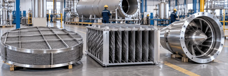
Actual performance depends on the selected internal geometry, gas and liquid properties, velocity, liquid loading, pressure drop, fouling tendency and drainage arrangement. Vendor-specific performance should be checked for the final design.
Separator Internals Are Part of the Process Design
Internal components are selected to control momentum, distribute flow, remove entrainment and drain collected liquid. The arrangement should follow the actual separation duty rather than a fixed internal package.
Inlet Diverter
Redirects the incoming two-phase stream and initiates bulk liquid separation by changing momentum.
Inlet Distributor
Reduces localized momentum and improves distribution when a simple diverter does not provide enough flow conditioning.
Flow Distribution / Calming Device
Helps create a more uniform gas velocity profile before downstream separation internals.
Wire Mesh Mist Eliminator
Provides high interception area for fine droplets that collide, coalesce and drain from the mesh structure.
Vane Pack
Uses repeated direction changes to create inertial droplet impaction while maintaining relatively open gas passages.
Cyclonic Internals
Apply centrifugal force to increase droplet separation and support high gas-handling capacity in suitable duties.
Liquid Drainage System
Transfers coalesced liquid away from the separation zone while reducing the chance of re-entrainment.
Vortex Control
Can be used around liquid outlets where vortex formation could disturb stable drainage or entrain gas into the liquid outlet.
Instrument Connections
Level, pressure, temperature and differential-pressure connections can be incorporated according to the operating philosophy.
The internal arrangement should be selected from the expected inlet momentum, liquid loading, droplet size, fouling tendency, pressure-drop allowance, drainage requirement and operating range.
Why Separators Fail Even When the Vessel Is Large Enough
Separator problems are often caused by flow behavior, liquid loading, internals or drainage rather than shell diameter alone. Select a failure mode below to see what changes inside the vessel and how the design should respond.
Gas velocity, liquid loading, level control and mist eliminator performance are evaluated around the primary operating condition.
High inlet momentum can create localized turbulence before the gas reaches the main separation zone.
Poor Inlet Distribution
High local momentum creates turbulence and an uneven gas velocity profile before the separator has time to stabilize the incoming two-phase flow.
Liquid can bypass the intended disengagement path and reach the mist eliminator with excessive momentum or uneven loading.
Inlet behavior, mist eliminator capacity, drainage, fouling tendency, slug volume and the full operating envelope need to be evaluated together.
Built Around Your Process — Not a Fixed Catalog Size
Gas liquid separators can be configured around project-specific pressure, dimensions, materials, internals, instrumentation and installation requirements. The final mechanical design should follow the actual process duty and purchaser specification.
Specific certification marks, stamps or third-party approvals should only be stated when they are included in the agreed project scope and supported by the required authorization.
Where Gas Liquid Separators Are Used — and What Buyers Often Miss
The same separator concept can serve very different process duties. Application context changes the required liquid handling, internals, materials, pressure rating and acceptable carryover.
Gas liquid separators are widely used for production separation, gas scrubbing, compressor suction protection and liquid knockout duties where free liquid and entrained droplets must be removed from a gas stream.
Click each item to see why it creates risk and what information should be supplied instead.
Diameter says little about liquid hold-up, slug capacity, internals, effective separation height or available disengagement volume.
Gas rate, liquid rate, operating pressure, expected slug volume, droplet requirement and installation constraints.
Separator sizing depends on actual gas volume and gas density, both of which change with operating pressure and temperature.
Standard gas flow plus actual operating pressure, operating temperature and gas composition or density.
Ninety-nine percent removal of 50 μm droplets is a very different requirement from ninety-nine percent removal of 5 μm droplets.
Target droplet size, outlet carryover requirement and the operating condition at which that performance is required.
Fine mesh can provide strong mist capture but may be vulnerable to fouling, solids, heavy liquid loading or drainage limitations.
Fouling tendency, solids content, liquid loading, turndown and pressure-drop allowance.
A mist eliminator can flood or lose drainage capacity even when the gas velocity itself appears acceptable.
Minimum, normal and maximum liquid loading reaching the fine-separation section.
A vessel can handle continuous liquid flow and still flood when a short-duration slug rapidly fills the available surge volume.
Expected slug volume, slug duration, control philosophy and available high-level margin.
Low-flow operation can reduce some internal separation mechanisms while high-flow operation can overload the same internal.
Realistic minimum, normal, maximum, startup and upset conditions where applicable.
The strongest RFQs describe the process problem first and the expected equipment configuration second. That gives the separator designer enough information to evaluate both gas-side and liquid-side limits.
Send Us the Data That Actually Determines the Separator
You do not need to finalize the vessel size before contacting us. Start with the process data you already know, then build the separator around the actual gas load, liquid load, separation requirement and mechanical constraints.
Gas-side sizing requires the actual operating condition, not only a standard volumetric flow number.
Send the Process Conditions You Have — We Can Work From There
Share your operating conditions, P&ID, equipment datasheet or existing separator information. Missing details can be clarified during engineering review.
The more realistic the operating data, the more accurate the separator proposal.