
Process Skid Systems
Integrate vessels, pumps, piping, valves, instrumentation and controls into one coordinated process package engineered around your P&ID, operating conditions, available space and site interfaces.
Rather than assembling individual components in the field, a process skid brings the critical equipment together on a common structural frame for controlled fabrication, inspection, testing and installation.
Process duty, materials, equipment scope, controls and applicable standards are defined according to the actual project requirements.
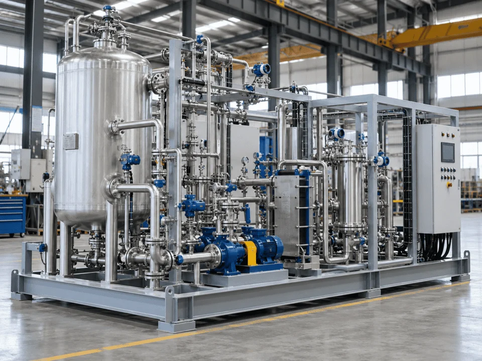
More Than Equipment Mounted on a Frame
A process skid is not simply a collection of pumps, vessels and valves installed on structural steel. The real engineering task is making every component operate as one coordinated system.
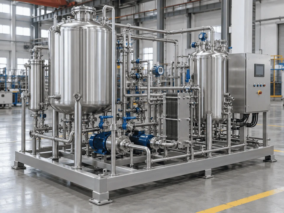
Process flow must be translated into equipment selection, piping routes, control logic, maintenance access, utility connections, structural support and clearly defined site interfaces.
Process Equipment
Vessels, tanks, filters, separators, heat exchangers and other equipment selected around the required process duty.
Fluid Handling
Pumps, process piping, manifolds, valves, drains, vents and connection points arranged according to required flow, pressure and operating conditions.
Instrumentation
Pressure, temperature, flow, level and other instruments used to monitor and control the process.
Controls & Electrical
Local control panels, PLC/HMI systems, junction boxes, field wiring and communication interfaces where included in the project scope.
Structural Integration
Base frames, equipment supports, pipe supports, lifting provisions and access structures developed around equipment loads, package layout and transport requirements.
The objective is to create a system that can be fabricated, transported, installed, operated and maintained without compromising process performance or accessibility.
A Reliable Process Skid Starts With the Design Basis
Selecting components before the process conditions are understood can create problems later in pump sizing, piping, material selection, control philosophy and package layout.
The same process function can require a completely different skid once flow, pressure, temperature, fluid properties, controls or site conditions change.
Define How the Process Actually Operates
Process data drives pump selection, piping size, equipment ratings, material compatibility and the overall system arrangement.
Define What the Skid Needs From the Plant
Utilities and control philosophy determine equipment interfaces, instrumentation architecture and what must be provided at site.
Design Around the Space the Skid Must Fit Into
Available space, access, environment and transport limitations should influence the package before the layout is frozen.
Confirm the Rules Before Detailed Engineering
Codes, customer specifications, testing and documentation requirements can materially change the engineering and fabrication scope.
Two skids may perform a similar process function but require completely different equipment, piping and controls because of differences in fluid properties, pressure, temperature, installation conditions or operating philosophy.
Define the System Boundary Before Detailed Engineering
A process skid becomes much easier to install when the limits between the packaged system and the customer's plant are clearly defined early in the project.
Equipment, piping, valves, instrumentation and controls engineered as one coordinated system.
Define What Enters and Leaves the Skid
Process tie-ins should be fixed before the layout is released so nozzle location, line routing and equipment orientation align with the actual plant connection points.
Match the Package to the Utilities Available at Site
Utility conditions must reflect the actual plant supply. Incorrect assumptions can change exchanger duty, valve sizing and overall system performance.
Confirm the Site Power Before Motors and Panels Are Finalized
Electrical supply affects motors, drives, panels and protection devices and should be confirmed before procurement.
Decide What the Skid Controls Locally and What the Plant Controls
Clear control boundaries prevent duplicated hardware, missing signals and late changes to the PLC or DCS architecture.
Connect the Skid to the Actual Installation Environment
Structural and site interfaces should be coordinated together with process and utility tie-ins rather than left until installation.
Nozzle elevations, utility conditions, electrical supply, control ownership and tie-in directions should be confirmed before fabrication is released.
From P&ID to an Integrated Skid Layout
A P&ID defines how the process should function. The skid design must convert that process logic into a physical system that can be fabricated, tested, transported, installed and maintained.
Confirm the Inputs Before Selecting Hardware
Review process conditions, required duty, project specifications, site utilities, installation constraints and the intended scope of supply.
Turn Process Logic Into an Engineering Scope
Review the P&ID to define major equipment, process lines, valves, instruments, control functions, drains, vents and battery limits.
Select Equipment Around the Required Duty
Size and select vessels, pumps, heat exchangers, filters and other equipment using the confirmed operating conditions and project requirements.
Build the Layout Around Flow, Access and Transport
Develop a preliminary arrangement that balances process flow, equipment footprint, piping length, maintenance clearance and shipping limits.
Develop the Mechanical and Piping Detail
Route process and utility piping, define supports, locate valves, drains and vents, and coordinate equipment connections with the structural frame.
Coordinate Instruments, Signals and Control Ownership
Define measurement points, local control functions, alarms, interlocks, panel scope and communication interfaces with the plant.
Review the Package Before Releasing It for Manufacture
Check the arrangement against operation, maintenance, fabrication, lifting, transport, installation and site-interface requirements.
What Can Be Integrated Into the Skid?
The equipment included in a process skid should follow the process duty rather than a fixed equipment list. A well-defined package integrates only the components required to perform, control and support the process.
Vessel type, volume, pressure rating, material, nozzle arrangement and internal configuration are selected around the process duty and operating conditions.
Key design inputs: Working volume · Pressure · Temperature · Material compatibility · Nozzle arrangementPump type should be selected according to required flow, differential pressure, viscosity, suction conditions, solids content and operating range.
Key design inputs: Flow · Head · NPSH · Viscosity · Solids · Minimum / maximum operating caseThermal equipment is integrated according to required duty, available utilities, allowable pressure drop and control requirements.
Key design inputs: Heat duty · Inlet / outlet temperatures · Utility conditions · ΔP · Fouling tendencyFiltration and separation equipment should be selected around contaminant loading, required removal efficiency, maintenance frequency and allowable pressure drop.
Key design inputs: Particle / phase characteristics · Loading · Removal target · Pressure drop · Service intervalPiping and valves should support required flow while maintaining accessibility, drainage, venting, support and appropriate material compatibility.
Key design inputs: Line size · Piping class · Valve function · Drain / vent philosophy · Support requirementsInstrumentation and controls can range from local indicators to fully automated packages integrated with the plant DCS or supervisory system.
Key design inputs: Control philosophy · I/O · Alarm / interlock requirements · Communication protocol · Panel scopeStructural design should account for equipment loads, piping loads, lifting conditions, transport loads, maintenance access and final installation conditions.
Key design inputs: Equipment weight · Operating weight · Lifting method · Transport condition · Foundation interfaceAdding unnecessary equipment increases skid size, piping complexity, procurement cost and maintenance requirements without improving process performance.
A Compact Skid Still Needs to Be Maintainable
Reducing footprint is useful, but compactness should not come at the expense of safe operation or practical maintenance. Equipment arrangement should consider how operators and maintenance teams will actually interact with the package after installation.
A smaller footprint is only an improvement when routine operation, inspection and component removal remain practical.
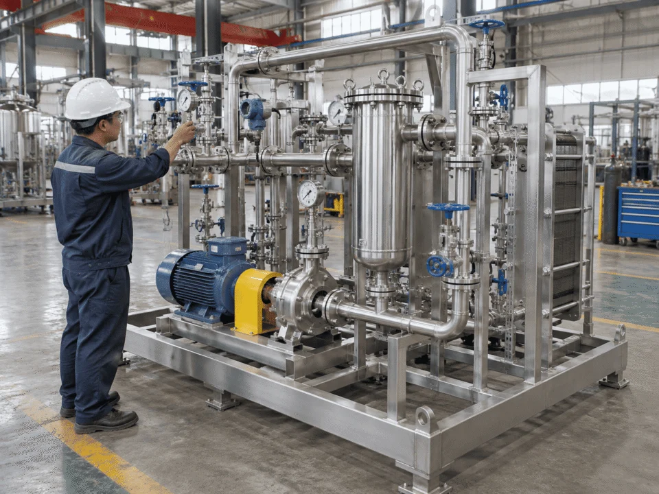
Check the Layout Before It Becomes Difficult to Change
Select a review point to see what should be checked during skid layout development.
Place Routine Controls Where Operators Can Actually Use Them
Frequently operated isolation and control valves should remain visible and reachable from a practical working position. Avoid arrangements where handwheels, actuators or service points are trapped behind piping or structural members.
Make Inspection and Calibration Practical
Local gauges, transmitters and indicators should be located where operators can inspect them and technicians can access process connections, manifolds or calibration points without unsafe reaching or unnecessary dismantling.
Allow the Pump to Be Serviced, Not Just Installed
Pump layout should allow access to motors, couplings, seals, bearing housings and removable wetted components. Suction and discharge piping should not make routine pump service unnecessarily difficult.
Reserve the Clearance Needed for Element Removal
Filter housings and strainers need realistic opening and removal space. Vertical housings may require overhead clearance, while horizontal elements may require a clear pull-out path.
Plan How Replaceable Equipment Leaves the Skid
Components such as pumps, motors, actuators and instruments should have a realistic removal path. A compact arrangement that requires cutting structural members or major process piping for replacement is not an efficient layout.
Resolve Low Points and High Points During Layout
Drain and vent requirements should be designed into the piping arrangement instead of being added after assembly. This helps support startup, shutdown, maintenance and safe system emptying.
Support the System Without Creating New Access Problems
Pipe supports should carry operating loads while keeping service areas open. Where thermal movement is relevant, the support concept should accommodate movement rather than unintentionally locking the system.
Design the Shipping Envelope Before Fabrication Is Complete
The ideal process arrangement is not automatically the ideal shipping arrangement. Package dimensions, total weight, center of gravity, lifting method, transport route and final site access can all affect the skid configuration.
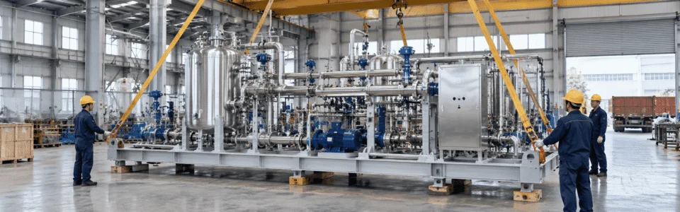
Know the Maximum Practical Package Size Before the Layout Is Locked
Overall length, width, height and shipping weight should be reviewed together with the planned transport method and route. A layout that performs well in the factory can still create unnecessary logistics problems if transport limits are considered too late.
Include protruding nozzles, panels, platforms and temporary shipping supports.
Differentiate dry, shipping and operating conditions where relevant.
Container, flat rack, truck or special transport can change the practical envelope.
Road, bridge, turning radius and delivery-site limitations should be reviewed early.
Design the Skid for How It Will Actually Be Handled
Lifting points, frame stiffness and handling method should reflect the real transport and installation sequence. Center of gravity should be understood so the package can be lifted and positioned in a controlled manner.
Locate and design points around the actual package weight and load path.
Heavy vessels, motors and dense piping can shift the COG away from the geometric center.
Crane, spreader beam, forklift or temporary lifting frame should be defined where applicable.
Shipping and lifting loads may require temporary support not needed during normal operation.
Make Sure the Skid Can Reach Its Final Position
Site access should be reviewed beyond the final footprint. Doors, corridors, roof openings, crane reach, foundation elevations and installation clearances can all affect the package design.
Confirm doors, gates, corridors and indoor movement routes.
Review lifting radius, overhead restrictions and final setting position.
Anchor pattern, support points and final elevation should match the site foundation.
Allow room for field piping, cable entry and utility connections after the skid is positioned.
A Large Package Does Not Always Need to Be Forced Onto One Frame
Where transport, lifting or site-access restrictions become excessive, the process can be divided into coordinated modules with clearly defined mechanical, piping, electrical and control interconnections.
Major vessels, piping and primary process equipment.
Transfer or circulation pumps grouped for access and service.
Thermal, air, water or auxiliary utility equipment.
Panels, remote I/O or supporting equipment separated where practical.
The correct answer depends on process integration, transport restrictions, lifting capability, site access and maintenance requirements.
Different Parts of the Skid May Follow Different Requirements
A process skid combines multiple equipment types. The package should therefore be reviewed by scope rather than described as complying with one single code by default.
Apply the Pressure Vessel Code to the Pressure-Containing Equipment It Governs
Where a vessel is within the jurisdiction of the applicable pressure vessel code or customer specification.
Design calculations, materials, welding, inspection, testing, documentation and certification scope.
Design pressure, design temperature, fluid service, material, code edition, stamping or certification requirement.
Review the Piping as Its Own Engineered System
For process and utility piping within the packaged system where the project specification requires an applicable piping code.
Pipe class, fittings, welding, examination, pressure testing, flexibility and fabrication records.
Design conditions, material class, corrosion allowance, joint type, examination level and test requirements.
Match Electrical Requirements to the Destination and Installation
Whenever motors, junction boxes, field wiring, cable systems or local electrical devices are included in the skid scope.
Component selection, wiring method, protection, grounding, enclosure rating and site connection details.
Voltage, phase, frequency, area classification, destination, cable standard and enclosure requirements.
Define the Panel Requirement Before Hardware Is Selected
Where the package includes PLC, HMI, motor controls, relays, protection devices or customer-required panel certification.
Panel construction, component selection, spacing, wiring, labeling, testing and documentation.
Panel location, environment, voltage, short-circuit requirements, customer-approved components and certification scope.
Area Classification Changes Equipment Selection Across the Skid
Where flammable gases, vapors or dusts create a classified electrical installation area.
Motors, instruments, junction boxes, cable entries, enclosures and protection methods.
Zone or class/division, gas or dust group, temperature class, ambient conditions and required certification.
Cleanability Requirements Should Be Defined by the Actual Process
For product-contact systems where cleanability, drainage, surface finish or sanitary connections are project requirements.
Materials, surface finish, welding, dead-leg control, drainability, fittings and cleaning philosophy.
Cleaning method, product-contact material, surface finish, gasket type, connection standard and inspection requirements.
Different components may be governed by different standards, while some requirements apply only when specifically called for by the project or destination.
Select Components Around the Service, Not Around a Standard BOM
Using stainless steel throughout the skid does not automatically make the system suitable for every process. Material and component selection should respond to the actual fluid, operating conditions, cleaning requirements and installation environment.
Match Wetted Materials to the Actual Chemical Service
Material choice should reflect corrosion potential, temperature, pressure, cleaning chemicals, solids content and external environment rather than a generic preference for stainless steel.
- Chemical compatibility
- Corrosion potential
- Temperature and pressure
- Chloride exposure
- Cleaning chemicals
- External environment
- Carbon steel
- 304 / 304L stainless steel
- 316 / 316L stainless steel
- Higher-alloy materials where required
A material that performs well in one service can be unsuitable in another because of chloride concentration, temperature, cleaning chemistry or mixed-fluid exposure.
Select the Pump Around the Hydraulic Duty
Pump type and size should reflect the actual process range, not just one nominal flow point.
- Minimum / normal / maximum flow
- Required discharge pressure
- Viscosity
- Solids content
- Suction conditions
- Operating turndown
- Centrifugal pumps
- Positive displacement pumps
- Metering pumps
- Circulation pumps
A skid should remain operable across the expected process range without forcing the pump into an unsuitable operating region.
Match Valve Function to the Actual Process Requirement
Isolation, throttling, control and pressure-protection functions require different valve characteristics.
- Isolation or control duty
- Pressure and temperature
- Fluid compatibility
- Required Cv / pressure drop
- Actuation requirement
- Fail position where applicable
- Ball valves
- Butterfly valves
- Globe / control valves
- Check valves
Valve selection should reflect what each line actually needs to do, not simply standardize every position to one construction.
Check Elastomer Compatibility Before Finalizing the Package
Gaskets, O-rings and mechanical-seal elastomers can become the weak point of an otherwise compatible system.
- Process chemical
- Operating temperature
- Cleaning fluid exposure
- Pressure cycling
- Required service life
- Product-contact requirements
- EPDM
- FKM / Viton-type materials
- PTFE
- Project-specific sealing materials
Seal compatibility must be checked independently against the process medium, temperature and cleaning chemistry.
Choose the Instrument Around the Measurement and Environment
Instrument selection should reflect measurement range, accuracy, process connection, installation location and area classification.
- Required measurement range
- Accuracy requirement
- Process pressure and temperature
- Wetted material
- Area classification
- Signal / communication type
- Pressure
- Temperature
- Flow
- Level
Two pressure transmitters may require very different materials, ranges, connections or protection depending on the actual service.
Process compatibility · Reliability · Maintainability · Project value
Verify the Package Before It Reaches the Site
One of the key advantages of a skid-mounted system is the ability to assemble, inspect and test major parts of the package under controlled factory conditions before shipment.
Confirm the Built Skid Matches the Approved Engineering
Check the Dimensions That Matter at Site
Verify Applicable Pressure-Containing Systems Before Shipment
Confirm Instruments and Electrical Scope Before Energization or Site Tie-In
Test the Control Logic at the Level the Package Requires
Close the Technical Record Before the Package Is Released
Do Not Test Every Skid the Same Way
A simple pump-and-piping package does not require the same FAT as a fully automated process system. Test depth should reflect the actual integration level and agreed project scope.
Required temporary utilities, test instruments, acceptance criteria and customer witness points can then be planned into the project instead of added at the end.
A Process Skid Is Not Complete Without Its Documentation
The physical package is only one part of the project. Engineering and quality records help the customer install, inspect, operate and maintain the system after delivery.
Major documentation requirements added late in the project can delay final handover.
Design Documents That Define the Package
Records That Show How the Package Was Built and Verified
Documents for Signals, Wiring and Control Integration
Records the Customer Uses After Delivery
Required drawings, quality records, certificates, control documents and final handover files can vary significantly by project, destination and customer requirement.
Process Skid Systems for Different Industrial Duties
The same skid concept can serve very different processes. Equipment selection, piping, materials, controls and package layout should be developed around the actual application rather than copied from a fixed industry template.
Chemical Processing Skids
Integrated packages can support transfer, circulation, filtration, mixing support, fluid conditioning and other chemical-process duties.
Petrochemical & Utility Skids
Skid-mounted packages can support fluid transfer, utility service, separation, conditioning and packaged process duties in demanding operating environments.
Pharmaceutical Process Skids
Process packages may support controlled transfer, filtration, temperature control, circulation and clean-process duties where material and cleaning requirements are important.
Food & Beverage Process Skids
Integrated skids can support liquid transfer, circulation, filtration, heating, cooling and related processing duties for food and beverage systems.
Water Treatment Process Skids
Process packages can integrate pumps, filters, tanks, piping, valves and instrumentation for conditioning, transfer, filtration and treatment processes.
New Energy Process Skids
Skid systems can support fluid handling, filtration, thermal control and chemical-processing operations used in new-energy and battery-material production.
Application categories help define the operating context, but the final skid configuration should still be based on process duty, site interfaces, materials, controls and project requirements.
Skid-Mounted or Field-Built?
A process skid is not automatically the best choice for every project. The right configuration depends on process integration, equipment size, transport restrictions, site access, shutdown requirements and how much work should be completed before the package reaches the plant.
Single Skid
Best when the process is compact, highly integrated and practical to transport as one package.
Multi-Module
Best when factory integration is still valuable but one frame becomes impractical for transport or lifting.
Field-Built
Best when equipment is widely distributed, exceptionally large or strongly constrained by existing plant geometry.
Keep Factory Integration Without Forcing Everything Onto One Frame
A large process system can still benefit from off-site fabrication when it is divided into coordinated modules with clearly defined interfaces.
What to Send for a Process Skid RFQ
A useful technical proposal requires more than a list of equipment. The clearer the process duty, system boundary and project requirements are, the easier it becomes to evaluate equipment selection, package layout and scope responsibility.
Start With the Conditions the Skid Must Handle
These inputs define the hydraulic duty, equipment rating, materials and process configuration.
Send Whatever Engineering Information Already Exists
Even preliminary drawings can help define scope boundaries and identify missing information early.
Define the Preferred Mechanical Scope Where Known
If these items are not fixed, they can be developed during technical clarification.
Clarify What the Skid Controls and What the Plant Controls
Control ownership and electrical interfaces should be understood before panel and instrument scope is finalized.
Design the Package Around the Actual Installation Conditions
Available space, utilities and access can change the physical arrangement as much as the process duty itself.
Confirm the Project Rules That Affect Scope and Delivery
Codes, inspection, FAT and document requirements should be known before commercial and technical scope is finalized.
You Can Start With Just Three Things
Send the Information You Already Have
A finished specification is not required to begin. Send your P&ID, process description, equipment list or preliminary layout for an initial scope discussion.
Build the Skid Around the Process — Not the Other Way Around
A reliable process skid starts with clear process conditions, system boundaries and project requirements. Send your P&ID, process data or equipment list and discuss how the vessels, pumps, piping, valves, instrumentation and controls can be integrated into a practical skid-mounted package.
Include your P&ID, process conditions, preferred materials, utilities, control requirements and installation constraints where available.