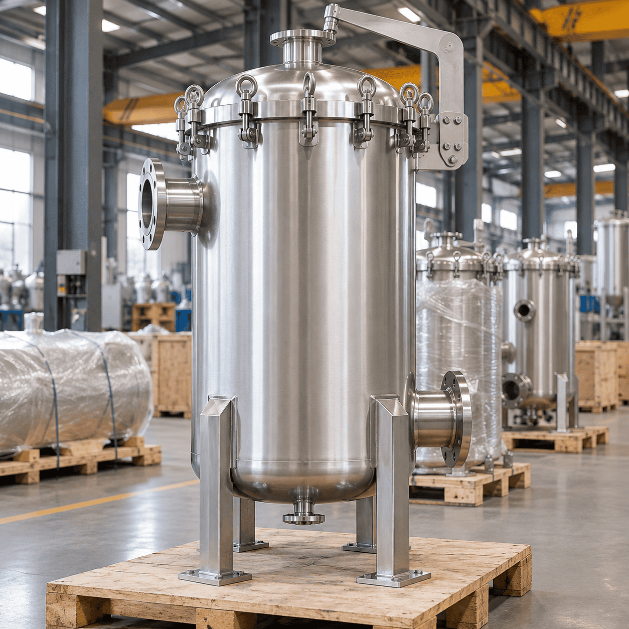
Custom Filter Vessels for Industrial Process Filtration
Engineered bag, cartridge and high-flow filter vessels for industrial liquid filtration, solids removal and process protection. ChannelVessel designs each vessel around flow, viscosity, solids loading, filter media, pressure drop, operating pressure, temperature and required outlet quality.
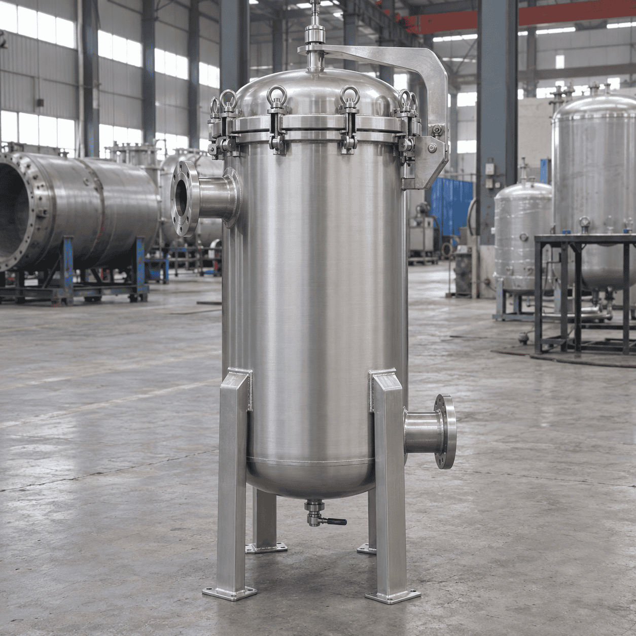
A Filter Vessel Is More Than a Pressure Housing
The filter media removes contaminants. The vessel creates the controlled pressure boundary, flow path and sealing arrangement that allow the filter element to perform correctly.

The vessel and the filter element solve different engineering problems.
A filter vessel does not perform filtration by itself. The bag or cartridge determines what is removed, while the vessel must contain process pressure, distribute flow, support the element and prevent contaminated fluid from bypassing the filtration media.
Determines particle retention, filtration efficiency, dirt-holding capacity, pressure drop and expected service life.
Creates the pressure boundary, directs the flow path, supports the element, maintains sealing and provides access for operation and maintenance.
A vessel can meet the required pressure rating and still deliver poor filtration. Internal sealing, element support and flow distribution must be engineered together with the pressure shell.
Choose the Right Filter Vessel Configuration
The correct vessel type depends on contaminant loading, required filtration level, available plant space, maintenance strategy and whether the process can stop for element replacement.
Bag Filter Vessels
Bag filter vessels are commonly selected for liquid processes with moderate to high solids loading and for coarse-to-medium filtration duties. Their relatively simple internal arrangement can provide high dirt-holding capacity and fast filter replacement.
Conventional Cartridge Filter Vessels
Cartridge vessels are generally preferred where finer particle control, larger filtration area or polishing performance is required. Multiple cartridges can be arranged inside one housing to increase usable filtration area without multiplying the number of separate vessels.
High-Flow Cartridge Filter Vessels
High-flow cartridges use larger-diameter, high-area elements to handle greater throughput with fewer cartridges than a conventional multi-round arrangement. They can reduce the number of elements operators must handle while keeping the filtration system compact.
Duplex Filter Vessels
Duplex filtration is selected when the process cannot be interrupted during routine element replacement. One vessel can remain in service while the second side is isolated, depressurized, drained and maintained.
When one bag or cartridge cannot provide enough usable area, multiple elements can be arranged inside a larger vessel. The final element count should be based on actual viscosity, solids loading, pressure drop and required service interval.
Start With the Filtration Duty, Not the Vessel Diameter
A reliable selection begins with the process conditions. These inputs determine the filter media, usable filtration area, number of elements, vessel configuration and pressure-boundary design.
Normal and maximum flow determine the hydraulic duty. Peak flow must be checked because a vessel that performs well at normal production can generate excessive differential pressure during short high-flow periods.
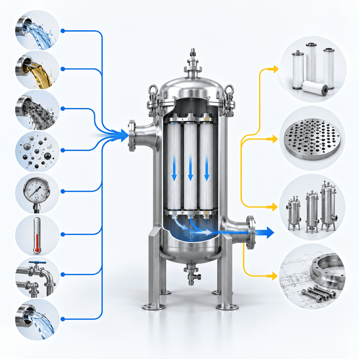
Bag, cartridge, high-flow or staged media is selected from the actual contamination and outlet target.
Required area follows the real hydraulic and solids-loading duty rather than a catalog maximum flow number.
Single, multi-element, standby or duplex arrangement is chosen around capacity and continuity requirements.
Pressure, temperature, materials, closure, nozzles and code requirements define the final pressure boundary.
Vessel diameter is an output of the engineering process—not the first sizing input. Detailed mechanical design should follow the confirmed filtration duty and process conditions.
Vessel Design Basics →Flow Rate Alone Is Not Enough to Size a Filter Vessel
Filter-vessel sizing is fundamentally a filtration-area problem before it becomes a vessel-diameter problem. The element count, allowable filtration flux and expected loading cycle should be checked before the pressure shell is finalized.
A first-pass estimate can divide the required process flow by the allowable flow through one selected filter element.
This relationship highlights the more important engineering question: how much effective filtration area is required at a realistic allowable flux.
Higher viscosity increases resistance through the filter media. A duty that is easy with water may require substantially more filter area when the process fluid is oil, resin or a concentrated chemical.
A slightly larger element arrangement can reduce filtration velocity, differential pressure and changeout frequency. Sizing should therefore be evaluated against operating cost and maintenance requirements—not only initial equipment price.
Micron Rating Alone Does Not Define Filtration Performance
A “10 μm filter” description does not tell the complete performance story. Media construction, rating method, removal efficiency and sealing quality all influence what actually reaches the clean side.
Nominal Micron Rating
A nominal rating generally describes approximate particle retention around the stated size. It should not automatically be interpreted as complete removal of every particle larger than the nominal value.
For hydraulic filter elements tested under ISO 16889 conditions, β200 corresponds to approximately 99.5% particle-removal efficiency at the stated particle size. This should not be applied universally to every bag or cartridge filter.
ISO 16889 Reference ↗
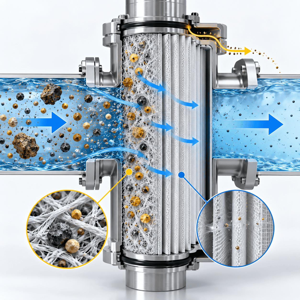
Good Filter Media Cannot Compensate for Bypass
Even a high-efficiency element will underperform if contaminated fluid can pass around the media. The vessel internals must maintain reliable separation between the dirty and clean sides throughout operation.
Filter Vessel Engineering & Customization
ChannelVessel can engineer the vessel shell, internals, filter-element interface, connections and support arrangement around the filtration duty, customer-selected element and project specification.
Configuration is selected around contamination loading, filtration target and operating continuity.
Large multi-bag arrangements can be engineered when greater filtration area is required.
Internals can also be designed around customer-selected cartridge dimensions.
Final quantity depends on element geometry, filtration area, viscosity, solids loading and vessel design.
Existing filter elements can be accommodated when dimensional and sealing data are provided.
Allowable temperature depends on vessel material, pressure, closure, seal and filter element.
Orientation is selected around footprint, maintenance clearance, element handling and process layout.
Closure selection should consider pressure, opening frequency, vessel diameter and operator handling.
Connection standard and pressure class can follow the project piping specification.
Nozzle orientation should follow actual piping routing, drainage and maintenance access.
Final elastomer or gasket selection follows fluid chemistry, temperature and cleaning conditions.
Connections can be provided for local pressure gauges, DP gauges, transmitters or high-DP alarms.
Manual or instrumented arrangements can be configured around filling, draining and maintenance procedures.
Surface treatment depends on material, corrosion environment, cleanliness and project specification.
Support arrangement is coordinated with vessel orientation, site loads and installation method.
Applicable code, inspection, documentation and stamping requirements should be confirmed during quotation.
Already Using a Specific Filter Element?
If you provide the element model, dimensions, length, end configuration and sealing details, the vessel internals can be engineered around the existing cartridge instead of forcing a new consumable format.
Need More Than a Standalone Vessel?
Filter vessels can be integrated with pumps, isolation valves, bypass piping, flowmeters, DP instrumentation, process piping and controls as a larger filtration package.
Material and Seal Selection Starts With the Process Fluid
Pressure rating alone does not determine the correct vessel material. Fluid chemistry, chloride concentration, pH, operating temperature, cleaning chemicals and the actual wetted components should be reviewed together.
Carbon Steel
Carbon steel can be a cost-effective choice for compatible industrial services where corrosion can be controlled through corrosion allowance, coating, lining or suitable process conditions.
Chloride concentration, temperature, pH, cleaning chemicals, stagnant conditions and crevice locations should still be reviewed before selecting 316L for the service.

Check Every Wetted Component
A corrosion-resistant shell does not solve the problem if the internal parts in contact with the process fluid use an unsuitable material. The wetted-material specification should cover the complete filtration path.
Seal Compatibility Can Become the Operating Limit
Even when the metal vessel is compatible with the fluid, an incorrectly selected gasket or O-ring can swell, harden, crack or lose sealing performance.
Final material selection should follow the actual process chemistry and temperature—not a generic “stainless steel is better” rule.
Material Selection Guide →Pressure Vessel Requirements Still Apply to Filter Housings
Filtration performance is only one part of the design. When the housing operates as pressure equipment, the pressure boundary, closure, temperature range, vacuum condition and credible overpressure scenarios must also be defined.
Design Pressure
Design pressure should reflect the credible maximum pressure condition and the required design margin. It is not simply the normal operating pressure copied into a datasheet.
MAWP
Maximum Allowable Working Pressure is established from the completed vessel geometry, materials and applicable code rules. It should not be confused with the process operating set point.
Design Temperature
Temperature affects material allowable stress, gasket compatibility, closure selection and the filter element itself. Maximum and minimum credible conditions should both be identified.
Vacuum Conditions
Vacuum can occur during draining, cooling, condensation, pump suction or blocked-vent conditions. Full or partial vacuum should be specified when it is a credible operating case.
Detailed code calculations, weld-joint rules, PWHT requirements and examination criteria belong in the technical standards and vessel-design resources rather than being repeated in full here.
Design for Maintenance Before the Vessel Is Fabricated
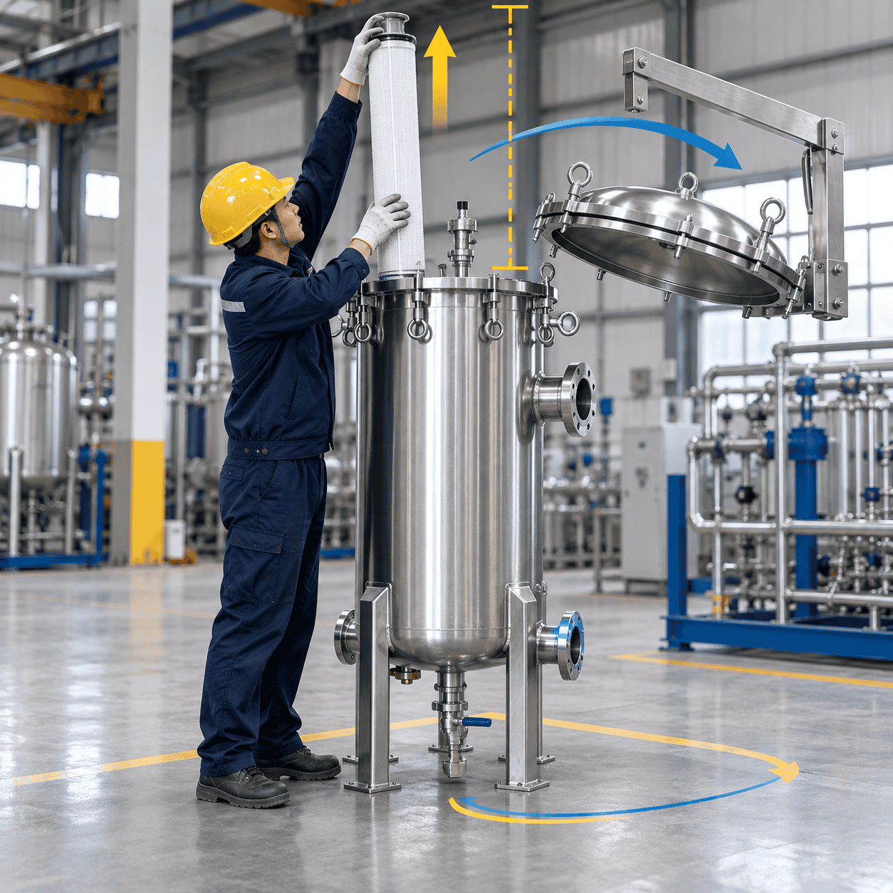
A filter vessel can be mechanically correct and still be difficult to operate if cartridge removal height, cover swing, draining, venting and operator access are ignored during layout.
Top-Entry Arrangement
A top-entry arrangement can improve flow into some bag-filter configurations and may simplify element seating and changeout. It can also reduce the need for operators to reach deeply into a vessel containing residual liquid.
- Check overhead pipework and cover access
- Coordinate inlet piping with the opening envelope
- Confirm drainage before element removal
- Verify lifting and handling space
Upstream and downstream pressure connections can support local gauges, DP gauges, transmitters or high-DP alarms. Final changeout limits should follow the selected element and the process requirement.
Check the Maintenance Envelope Before Fabrication
These items are easier to correct in the drawing stage than after the filter vessel is installed beneath pipework, platforms or cable trays.
A vessel that can be isolated, drained, vented, opened and serviced safely will usually cost less to operate over its lifetime than one optimized only for minimum purchase price.
Maintenance & Troubleshooting →Single, Parallel, Duplex or Staged Filtration?
The vessel arrangement should follow the operating requirement. Flow capacity, redundancy, maintenance continuity and contaminant distribution can all change the most suitable filtration layout.
Multi-vessel filtration should be engineered together with the isolation valves, switching sequence, bypass philosophy, drains, vents and instrumentation—not treated as a vessel-only decision.
Custom Separation Systems →Filter Vessel Design Changes With the Process
The same filter vessel should not be copied from one industry to another without reviewing corrosion, solids loading, operating pressure, cleanliness, maintenance strategy and documentation requirements.

Chemical Industry
Chemical filtration can involve corrosive liquids, solvents, resins and solids-bearing streams. Material compatibility and seal selection often become primary design inputs.

Petrochemical Industry
Petrochemical filtration can combine elevated pressure, hydrocarbon compatibility and continuous production requirements within one service.
Oil & Gas Industry
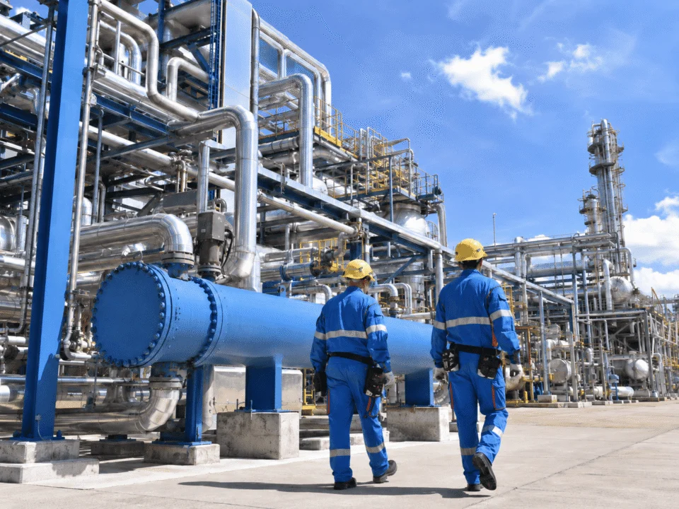
Filter vessels may handle fuels, lubricants, process chemicals and utility streams where pressure, solids and service continuity must be considered together.
Water Treatment
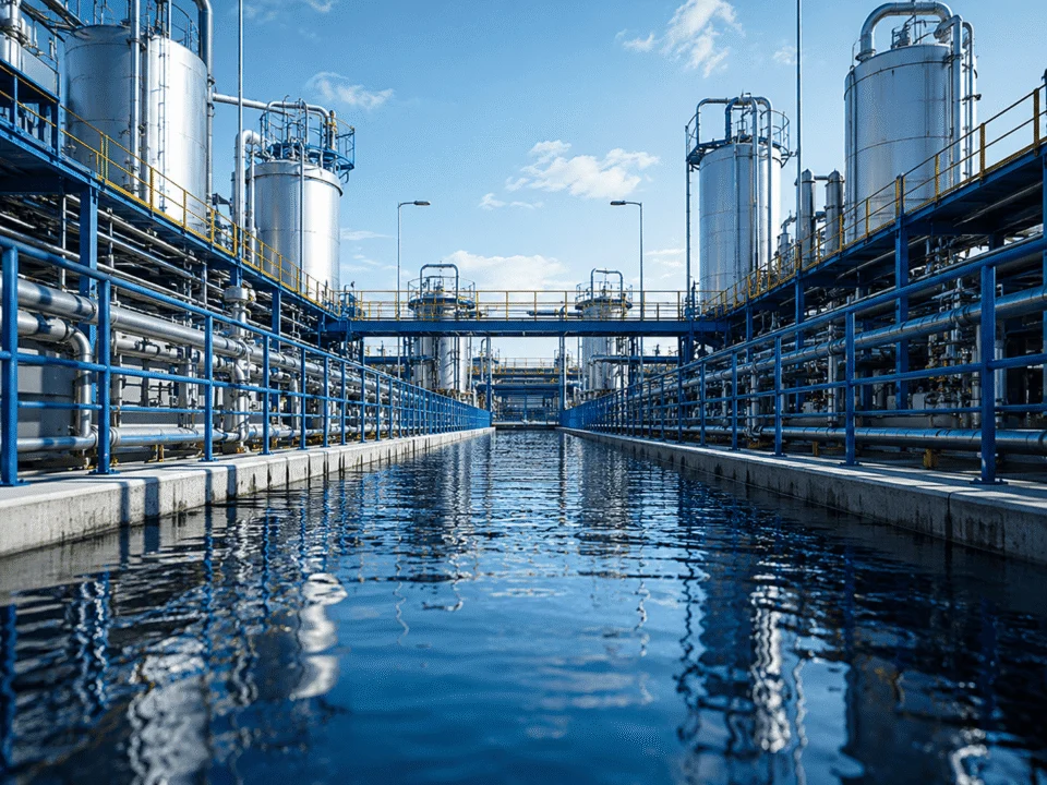
Water-treatment filter vessels can remove suspended solids and protect pumps, membranes and downstream equipment from premature fouling.

Food & Beverage Industry
Food and beverage filtration places greater emphasis on cleanability, drainability, suitable elastomers and product-contact surface requirements.

Pharmaceutical Industry
Pharmaceutical filtration can require tighter control of material traceability, surface finish, cleanability, hygienic connections and project documentation.
Filter Vessel Quality Is Built Before the Pressure Test
Reliable filter vessels depend on controlled materials, qualified welding, dimensional accuracy, inspection and complete documentation throughout fabrication—not only on the final hydrotest.
Material identification and PMI can be included where the project or service requires additional verification.
Pressure-retaining welds can be manufactured under qualified procedures and personnel where required by the code or project.
The inspection method and extent should match the vessel design, material, service and agreed inspection plan.
Tube sheets, baskets, closure alignment and skid interfaces should be checked before final release.
Hydrotesting is commonly used to verify pressure-boundary integrity. Alternative test methods should follow the applicable code and approved procedure.
Know What You Receive With the Vessel
Documentation can be adjusted to the customer, EPC, third-party inspection and project quality requirements.
Witness points, hold points and document-review requirements can be incorporated when they are identified in the purchase specification.
Inspection scope, code stamping, documentation format and customer witness requirements are much easier to control when they are defined during quotation and drawing approval.
You Do Not Need a Complete Datasheet to Start
A preliminary filter-vessel selection can begin with a small amount of process information. More detailed data can be added later to refine the element count, vessel geometry, material, code and maintenance arrangement.

If You Already Have Project Documents, Send Them
We can review the existing process information and develop the vessel configuration around the actual filtration duty instead of asking you to rebuild the specification from the beginning.
You do not need every engineering parameter before contacting us. Send the basic process conditions or your existing drawings first, and the remaining design inputs can be confirmed during technical review.
Filter Vessel FAQs
These are the questions that most often affect vessel selection, compatibility, code requirements and project quotation.
The terms are often used interchangeably. “Filter housing” is common for standard equipment, while “filter vessel” is often used for larger, engineered or pressure-code designs where the shell, internals, closure and documentation are customized to the process duty.
Bag filters are commonly selected for higher solids loading and coarse-to-medium filtration. Cartridge filters are generally preferred for finer filtration, larger media area or polishing duties. The actual decision should also consider viscosity, pressure drop, service interval and operating cost.
Yes. If you provide the cartridge dimensions, length, end configuration, sealing arrangement and element datasheet, the internal tube sheet, hold-down and sealing interface can be engineered around the existing consumable format.
Common arrangements include DOE, SOE, 222 and 226 interfaces. Project-specific cartridge dimensions and sealing connections can also be considered when sufficient dimensional and performance data are available.
It depends on pressure, jurisdiction, project specification and the applicable regulatory requirements. Where ASME Section VIII is specified, the vessel can be engineered around those requirements. See our Codes & Standards resource for more detail.
Code stamping, inspection, documentation and third-party requirements can be reviewed during quotation when they are part of the purchase specification. The exact code edition, stamp requirement and documentation scope should be confirmed before fabrication.
Yes, when full vacuum or another external-pressure condition is specified as a design case. Vacuum should be identified before fabrication because it can materially change the required shell and reinforcement design.
The required maintenance height depends on cartridge length, the internal hold-down arrangement, cover geometry and operator handling space. A 40-inch cartridge vessel should be checked against overhead pipework, platforms and structural steel before the final site layout is frozen.
Yes. Filter vessels can be integrated with pumps, isolation valves, bypass piping, flowmeters, differential-pressure monitoring and controls as part of a duplex or packaged filtration system. See Custom Separation Systems.
For a preliminary selection, provide the fluid, flow rate, operating pressure, operating temperature, filtration target and preferred material if known. Viscosity, solids loading, design conditions, filter-element details and drawings can be added later for final engineering.
Send Your Process Conditions — We’ll Size the Vessel Around the Duty
A reliable filter vessel starts with the process, not a catalog model number. Send the basic operating conditions or your existing drawings, and the vessel shell, filter-element interface, internals, connections and maintenance arrangement can be engineered around the actual filtration duty.
Send it with your inquiry. Existing project documents can help confirm nozzle orientation, element interface, available space and the correct vessel configuration faster.