ChannelVessel Intelligent Equipment Co., Ltd. Contact Us
Industrial Process Equipment

Industrial Evaporators for Process Concentration

ChannelVessel supplies custom industrial evaporators for process-liquid concentration, wastewater volume reduction and recovery-related duties. Falling-film and forced-circulation configurations are selected around your feed, target concentration, temperature limits and available utilities.

Feed-specific configuration Material and utility options Defined equipment scope
Define the evaporation duty first, then align the equipment, materials and supply scope with the process. Explore our heat exchangers.
Falling Film Forced Circulation Vacuum MVR / Multi-effect
Project basis
Feed → Duty → Configuration
Project basis
Feed → Duty → Configuration
Falling Film Forced Circulation Vacuum MVR / Multi-effect
Define the Process Duty

Start With the Evaporation Duty, Not the Equipment Type

An evaporator is selected to achieve a separation task, not simply to match a tank size. Identify what enters the system, what must remain in the concentrate and what quality is required from the recovered vapor or condensate.

Feed →

Define What Enters the System

Provide the composition, flow range, temperature and solids content. Identify solvents, suspended particles and components that may become more difficult to handle as concentration increases.

Composition · Flow · Temperature · Solids · Volatile components
Concentrate →

Define the Required Product Condition

State the required final concentration and whether the discharge must remain pumpable. Specify product-quality limits and whether crystal formation is acceptable or must be avoided.

Final concentration · Pumpability · Product quality · Crystallization limits
Vapor / Condensate →

Define What Happens to the Recovered Stream

Clarify whether the objective is water recovery, solvent collection or simply liquid-volume reduction. Set the intended use and required quality before selecting the separation and condensation arrangement.

Recovery objective · Condensate quality · Downstream treatment · Reuse target
!
Evaporation is only one separation step. It does not automatically provide fractional distillation, dry solids or a complete zero-liquid-discharge process. Additional recovery, crystallization or downstream treatment may be required.
Mass Balance Before Equipment Sizing

Calculate Evaporation Duty Before Sizing the Equipment

Feed capacity and evaporation capacity describe different quantities. Specify the incoming liquid, concentrated product and solvent removed separately so that every supplier is pricing the same process duty.

Worked Example: Concentrating an Aqueous Feed

Feed flow5,000 kg/h
Feed nonvolatile solids10 wt%
Target nonvolatile solids50 wt%
Nonvolatile solids retained500 kg/h
Concentrate flow1,000 kg/h
Water evaporation rate4,000 kg/h
Concentrate flow: 5,000 × 0.10 ÷ 0.50 = 1,000 kg/h
Evaporation duty: 5,000 − 1,000 = 4,000 kg/h

The Same Feed Produces a Different Duty at a Different Target
25 wt% target
3,000 kg/h evaporation
40 wt% target
3,750 kg/h evaporation
50 wt% target
4,000 kg/h evaporation
Better RFQ wording
We need to process 5,000 kg/h of aqueous feed from 10 wt% to 50 wt% nonvolatile solids, requiring approximately 4,000 kg/h of water evaporation.
Assumptions: steady operation, no reaction, no solids loss and negligible liquid entrainment. Mixed solvents, volatile solutes and batch concentration require a more detailed balance. This is an illustrative calculation, not a ChannelVessel project or equipment guarantee.
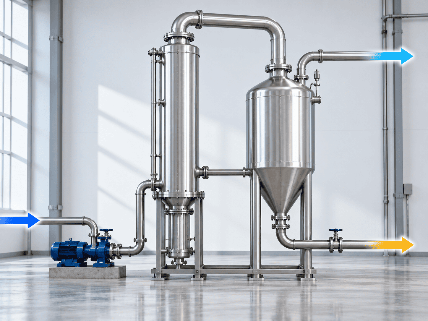
Industrial evaporator mass balance showing feed entering an evaporation system with vapor and concentrate outlets
Feed
5,000 kg/h
Water vapor removed
4,000 kg/h
Concentrate
1,000 kg/h
Configuration Selection

Match the Evaporator Configuration to the Feed

Select the liquid-handling arrangement around the most demanding expected concentrate, not only the incoming feed. Falling-film and forced-circulation systems solve different operating problems, and neither is automatically the better choice for every liquid.

Feed conditionFalling filmForced circulationConfirm before selection
Heat-sensitive liquidOften a candidateRequires reviewMaximum temperature, exposure time and product stability
Low viscosity, low solidsOften well suitedPossibleDistribution, wetting, fouling tendency and turndown
Increasing final viscosityNeeds evaluationOften consideredViscosity at the actual final concentration and temperature
Scaling or precipitationUse cautionOften evaluatedSolubility limits, deposit behavior and cleaning strategy
Suspended solids or crystalsNeeds evaluationOften preferredParticle loading, crystal size, passage size and pump suitability
Shear-sensitive productCan be attractiveCheck recirculationAllowable shear, pump selection and product degradation limits
Do not mix the categories

Configuration, pressure and heat recovery describe different things

Falling film and forced circulation describe how liquid moves through the evaporator. Vacuum describes operating pressure. Multiple effects, TVR and MVR describe how heat or vapor is reused.

Related equipment

Heat-transfer hardware still has to match the duty

Heating-surface geometry, allowable pressure drop and cleanability should be reviewed together with the liquid-handling arrangement.

Explore Shell & Tube Heat Exchangers
Screening guidance only: falling film is not automatically correct for every heat-sensitive liquid, and forced circulation does not eliminate fouling. Final selection should use the actual feed composition, final concentration, viscosity, solids behavior and cleaning requirements.
Vacuum, Boiling Point and Vapor Load

Vacuum Lowers Boiling Temperature—Not the Need for Heat

Lower absolute pressure reduces the boiling temperature of water, which can help when the process liquid is temperature-sensitive. It does not remove the latent heat required for evaporation, and lower-temperature vapor also occupies more volume per kilogram.

Pure Water Saturation Reference

TemperatureSaturation pressureLatent heatSaturated vapor volume
40°C7.385 kPa(a)2,406.0 kJ/kg19.515 m³/kg
60°C19.946 kPa(a)2,357.7 kJ/kg7.667 m³/kg
80°C47.414 kPa(a)2,308.0 kJ/kg3.405 m³/kg
100°C101.42 kPa(a)2,256.4 kJ/kg1.672 m³/kg
Pure-water saturation data shown as a design reference. Actual process solutions can have a higher boiling temperature because of composition and boiling-point elevation. NIST water and steam properties.
Illustrative latent-duty estimate
≈2.62 MW
For 4,000 kg/h of water evaporation at 60°C, using the listed latent heat only. Feed heating and other loads are excluded.
Vapor-volume comparison
≈11.7×
Saturated water vapor occupies about 11.7 times more volume per kilogram at 40°C than at 100°C. This does not mean the whole system must be 11.7 times larger.
Heat-transfer duty is not compressor power
Keep thermal duty and purchased utility demand separate
4,000 × 2,357.7 ÷ 3,600 ≈ 2,620 kW
This is an evaporation heat-transfer estimate for the worked example. It is not the electrical power requirement of an MVR compressor and should not be presented as MVR consumption.
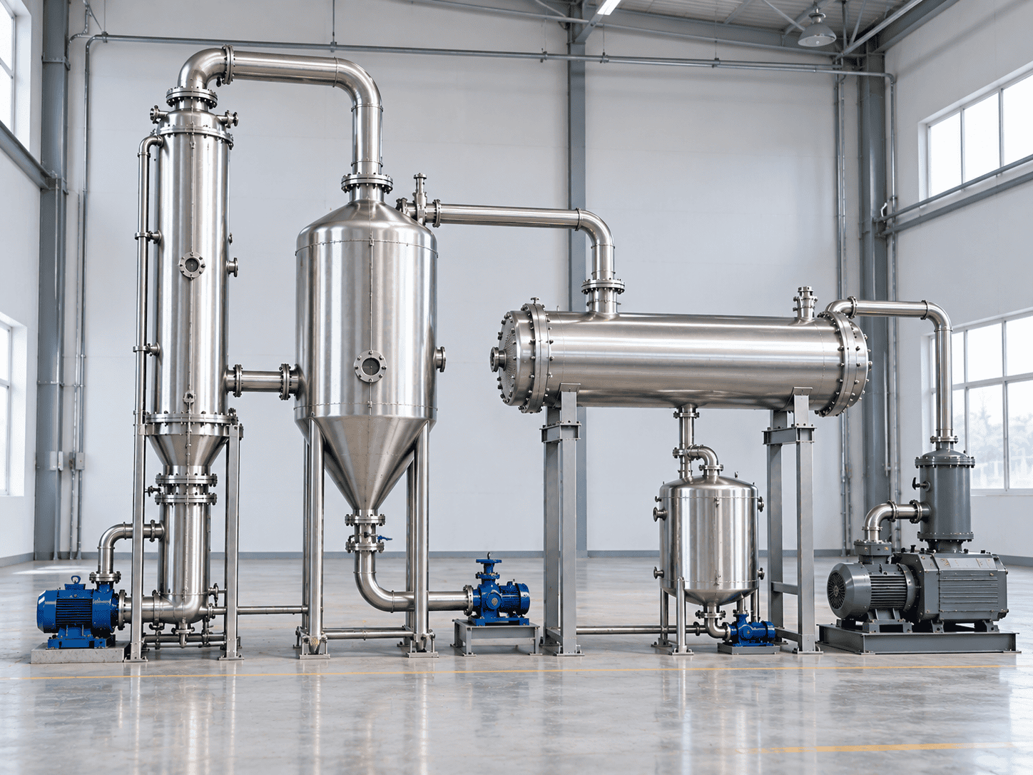
Simplified industrial vacuum evaporation system with evaporator, separator, condenser and vacuum equipment
Evaporator
Separator
Condenser
Vacuum System
Effective Temperature Difference

Account for Boiling-Point Elevation and Heat-Transfer Losses

A process solution can boil above the saturation temperature of pure water at the same pressure. As concentration rises, boiling-point elevation, viscosity and fouling can reduce the effective temperature difference or the overall heat-transfer coefficient used to size the evaporator.

Why this matters

The heating-steam temperature is not the complete driving force

The designer should consider the actual boiling temperature of the concentrated liquid, pressure losses through the system and the temperature profile across the selected effect or heating surface.

Simplified heat-transfer relationship
Q = U × A × ΔT
Q Required heat-transfer duty
U Overall heat-transfer coefficient
A Installed heat-transfer area
ΔT Effective temperature difference
Buyer question to ask
Which concentration, heat-transfer coefficient and effective temperature difference were used to size the heating surface?

A Smaller Effective ΔT Can Require More Surface Area

Assume the required heat duty and overall heat-transfer coefficient stay unchanged. If the effective temperature difference falls from 20 K to 15 K, the theoretical area rises in inverse proportion.

Original effective ΔT
20 K
→
Reduced effective ΔT
15 K
Illustrative area ratio
20 ÷ 15 = 1.33 → about 33% more area
The 5 K reduction is only an example. Real sizing should use the actual concentration profile, boiling-point elevation, viscosity, fouling allowance and pressure losses.
Steam, Multiple Effects, TVR and MVR

Compare Heating Concepts on the Same Evaporation Basis

Compare utilities per tonne of water evaporated, not per tonne of feed. Also confirm whether the published number includes pumps, vacuum equipment, compressors, cooling systems and start-up or supplementary heating.

Published Engineering Reference Values

Heating conceptSteam referenceElectricity reference
Conventional single effect≈1.00 t steam / t water evaporatedAuxiliary loads depend on package scope
Double effect≈0.50 t/tAuxiliary loads depend on package scope
Triple effect≈0.33 t/tAuxiliary loads depend on package scope
Four effects≈0.25 t/tAuxiliary loads depend on package scope
TVR reference arrangement≈0.50 t/t, design-dependentUsually not the primary energy input
MVR reference arrangementLow supplementary steam demand, condition-dependent≈30–50 kWh/t water evaporated
These values are contextual engineering references, not universal guarantees or ChannelVessel performance commitments. Final consumption depends on feed properties, temperature lift, compression duty, operating range and the complete equipment boundary. GEA thermal-separation heating options.
Apply one basis to the 4,000 kg/h worked example
Illustrative utility comparison
Single effect
≈4.00 t/h steam
Triple effect
≈1.32 t/h steam
MVR reference
≈120–200 kW
These are separate illustrative estimates based on the reference factors above. They are not predictions for a specific feed and do not replace a project heat-and-mass balance.
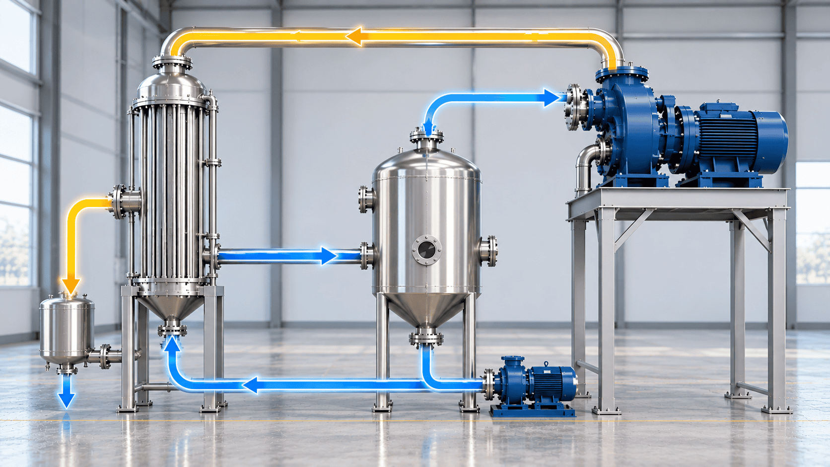
Simplified MVR heat recovery concept showing separator vapor, compressor and vapor return to the evaporator heating side
Separator Vapor
MVR Compressor
Heating Side
Condensate
Simplified MVR heat-recovery concept. Final piping, heat-exchanger connections and condensate routing depend on the selected process and equipment design.

Choose for the Site, Not the Label

Available steam pressure and steam price
Electricity tariff and demand charges
Annual operating hours and load stability
Required temperature lift and vapor compression duty
Cleaning, maintenance and equipment complexity
Installed cost versus expected operating cost
Explore Heat Exchangers
Custom Design Range

Custom Evaporator Options Start With the Process Data

ChannelVessel can configure the evaporator around the agreed process duty, materials, utility conditions and package scope. The options below define what can be evaluated during project engineering; they are not automatically included in every quotation.

Liquid-handling configuration
Falling Film or Forced Circulation
Other arrangements can be reviewed where the feed behavior or project objective requires a different approach.
Effect arrangement
Single · Double · Triple · Multi-effect
The selected number of effects should follow the heat balance, utility conditions, operating hours and economic comparison.
Heat-use concept
Conventional · TVR · MVR
Heat recovery is evaluated around the available temperature lift, steam conditions, electrical cost and operating profile.
Product-contact materials
304 / 304L · 316L · 2205 · Titanium
Final material selection depends on chemistry, chloride level, temperature, concentration and cleaning conditions.
Operating mode
Continuous or Batch by Duty
The selected mode depends on throughput, product sensitivity, load variation, cleaning strategy and downstream handling.
Automation and package scope
PLC Controls · Instruments · Integrated Equipment
Controls, piping, vacuum equipment, condenser, platforms and auxiliary systems are defined in the agreed equipment list.
Feed composition
Full composition, solvent identity, salts, corrosive components and known hazardous constituents.
Flow and concentration range
Minimum, normal and maximum feed flow, feed concentration and required final concentration.
Physical properties
Density and viscosity at relevant temperatures and concentrations, especially near the target concentration.
Boiling behavior
Boiling-point elevation, vapor-pressure information or available laboratory and pilot-test data.
Solids and deposits
Suspended solids, expected crystals, scaling history, precipitation temperature and cleaning experience.
Temperature and product limits
Maximum allowable temperature, thermal sensitivity, shear limits and required product-quality conditions.
Foaming and condensate target
Known foaming tendency, volatile components and the required quality or intended use of recovered condensate.
Utilities and operating profile
Steam, electricity, cooling media, annual operating hours, load variation and start-stop frequency.
Cleaning and maintenance
CIP expectations, manual access, drainage requirements, cleaning chemicals and maintenance constraints.
Site and delivery requirements
Installation space, access, electrical supply, design basis, documentation needs and included site services.
Unknown data does not have to stop the inquiry. Mark it as unknown so the review can distinguish confirmed process information from properties that may require assumptions or testing.
Supply Scope and System Boundary

Define What Is Included Before Comparing Evaporator Quotations

One quotation may cover the core evaporation equipment only, while another includes vacuum equipment, condensers, pumps, controls and package integration. Compare the equipment list and connection points before comparing the total price.

Core evaporation equipment

Define the heater, separator and circulation arrangement

State the evaporator body or heater, vapor-liquid separator, distributor where applicable, circulation loop, local valves and instruments included in the core supply.
Auxiliary equipment

Identify condensation, vacuum and material-handling equipment

Confirm feed pumps, product pumps, condenser, condensate handling, vacuum equipment and any equipment required for vapor recovery or heat reuse.
Integration and services

Mark every project item as included, optional or by others
Define package piping, structural supports, platforms, insulation, PLC controls, instruments, factory tests, documentation, site work and commissioning responsibilities.
Keep the interfaces visible
Utility and process connections should have a named battery limit
Identify where steam, electricity, cooling media, feed, product, vapor and condensate connect to the supplied package. Heating-steam condensate and process condensate should be identified separately unless the design specifically combines them.
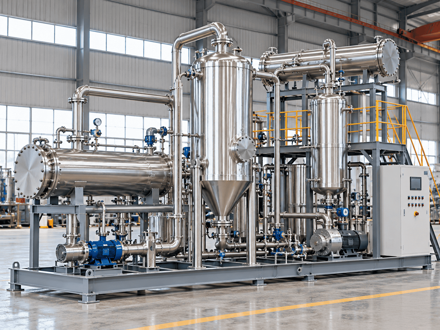
Complete industrial evaporation system with evaporator, separator, heat exchangers, pumps, piping, controls and access platform
Core Equipment
Evaporator + Separator
Auxiliary Equipment
Condenser + Pumps + Vacuum
Integration
Piping + Controls + Access
Included
Equipment listed in the agreed scope
Optional
Add only when the project requires it
By others
Show exclusions and connection points clearly
A lower equipment price can simply reflect a narrower supply scope. Normalize the equipment list, interfaces and project responsibilities before comparing offers.
Long-Term Operating Stability

Plan for Fouling, Foaming, Carryover and Cleaning

Initial evaporation capacity is only part of the design problem. The equipment should also be reviewed for what happens after hours or days of concentration, when deposits, foam, entrainment or cleaning requirements begin to affect performance.

Fouling and Scaling
What may happen
Deposits reduce heat transfer, increase temperature differences and shorten the operating interval between cleanings.
What to investigate
Feed chemistry, solubility limits, surface temperature, supersaturation and the way concentration changes through the system.
Design response
Select the configuration, velocity, cleaning access and fouling allowance around the actual deposit mechanism.
Foaming
What may happen
Foam can destabilize liquid level, occupy separator volume and increase the risk of liquid entering the vapor path.
What to investigate
Surfactants, proteins, organics, gas release, concentration effects and any proven antifoam limitations.
Design response
Review separator volume, liquid level control, operating margin and process-compatible foam-control measures.
Liquid Carryover and Condensate Quality
What may happen
Entrained droplets can carry product into the vapor stream and affect condensate quality or downstream equipment.
What to investigate
Vapor velocity, droplet loading, separator performance and volatile components that can pass into the vapor phase.
Design response
Define separation, demisting and condensate sampling requirements around the required recovered-stream quality.
Cleaning and Maintenance Access
What may happen
A theoretically efficient design can become expensive to operate if deposits are difficult to remove or access is restricted.
What to investigate
Cleaning chemicals, CIP expectations, manual access, drainage, isolation and the maintenance interval expected by the plant.
Design response
Provide cleanable flow paths, required access points, drainability and maintenance clearance in the equipment layout.
Droplet removal and removal of dissolved volatile components are different problems. A demister can reduce entrained liquid, but it does not guarantee that volatile contaminants will be absent from the condensate.
Materials, Mechanical Design and Documentation

Design for the Actual Concentrate, Pressure and Project Basis

Material compatibility and mechanical design should follow the real process conditions, not only the incoming feed. Concentration changes chemistry, vacuum creates external-pressure loads and the purchase specification determines what manufacturing and inspection records are required.

Material selection

Select for the concentrated liquid and cleaning conditions

Review chloride level, acids, alkalis, solvents, temperature, final concentration, deposits and cleaning chemistry together. A grade suitable for the dilute feed is not automatically suitable after concentration.
304 / 304L 316L Duplex 2205 Titanium
Mechanical load cases

Check pressure, vacuum and thermal loads separately

Define normal operating pressure and temperature, design pressure and temperature, full or partial vacuum, differential pressure, thermal expansion, support loads and connected-piping loads where applicable.
Project documentation

State the required records before fabrication starts
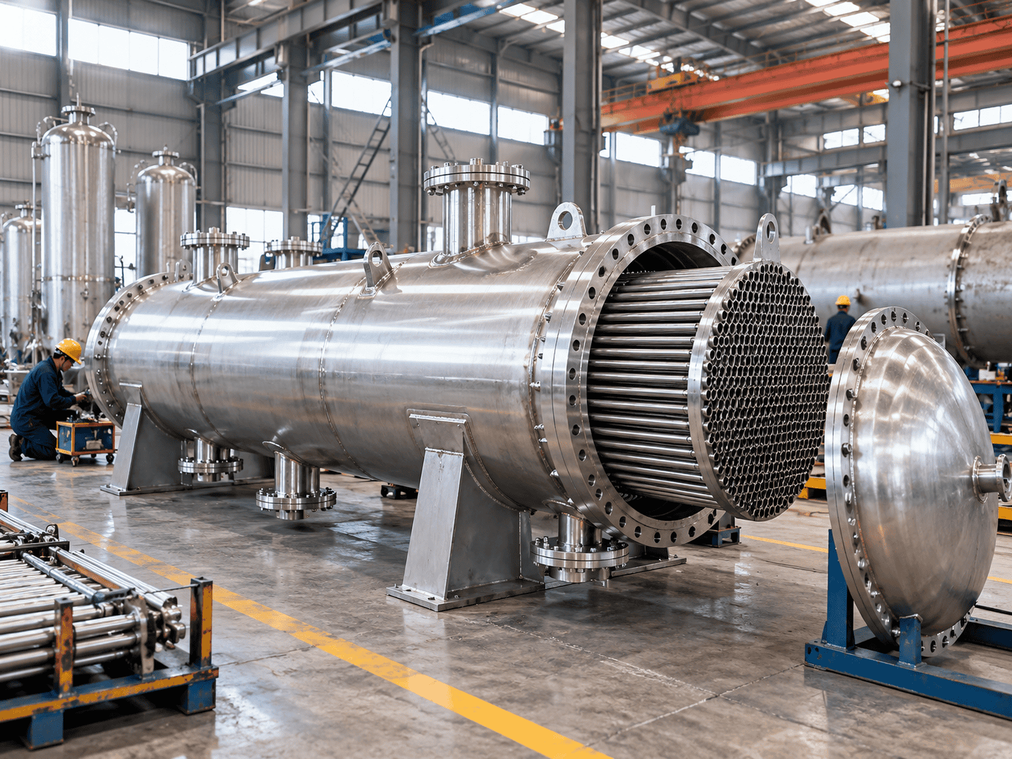
Define drawings, material traceability, welding records, inspection requirements, pressure or leak testing and any project-specific code or certification requirements in the purchase specification.
Code reference and manufacturer certification are not the same statement
If ASME BPVC Section VIII or another construction basis applies, the project should identify the edition, scope and required certification. Referring to a design code alone does not prove that a vessel is code-stamped or that a manufacturer holds a specific certification.
Stainless steel shell and tube heat transfer equipment during fabrication with visible tubesheet, tube bundle, flanges and vessel shell
Stainless Steel Heat-Transfer Equipment During Fabrication Illustrative manufacturing view showing shell, tubesheet, tube bundle, flanges and supports. Final fabrication and inspection records follow the agreed project specification.
Material
Traceability to agreed specification
Welding
Records to project requirements
Inspection
Defined hold and witness points
Testing
Pressure / leak test as applicable
Manufacturing evidence should match the purchase specification. The exact document package depends on the agreed equipment scope, design basis and customer requirements.
Quotation Review and Performance Acceptance

Compare Evaporator Quotations on the Same Technical Basis

Different equipment designs can both be technically acceptable, but their prices are only comparable when the process basis, utility boundary, equipment scope and performance test conditions are defined on the same basis.

Normalize the Technical Scope Before Comparing Price

Comparison itemWhat should be statedWhy it matters
Process basisFeed composition, flow, feed temperature, feed concentration, target concentration and required evaporation rateConfirms the same duty
Thermal basisOperating pressure, boiling temperature, effective ΔT, heat-transfer assumptions and fouling allowanceExplains sizing differences
Equipment basisConfiguration, materials, number of effects, heating surface, pumps, condenser, vacuum system and included instrumentsPrevents scope mismatch
Utility basisSteam conditions, electrical boundary, cooling demand, compressed air and all auxiliary loads included in the stated consumptionMakes OPEX comparable
Delivery basisControls, piping, structure, insulation, documentation, commissioning, site work and clearly stated exclusionsDefines the real package price
Acceptance basisTest feed, steady-state definition, duration, sampling method, evaporation rate, concentration target and utility measurement methodDefines what “meets performance” means
A clean-water test is not automatically proof of process performance. Viscosity, foaming, boiling-point elevation, scaling and solids behavior can change the operating result on the actual feed.
Applications, FAQs and Project Review

Evaporation Duties Across Process Industries

Industry names help describe the application, but the actual evaporator design still depends on feed chemistry, solids behavior, temperature limits, target concentration and the required quality of the recovered stream.
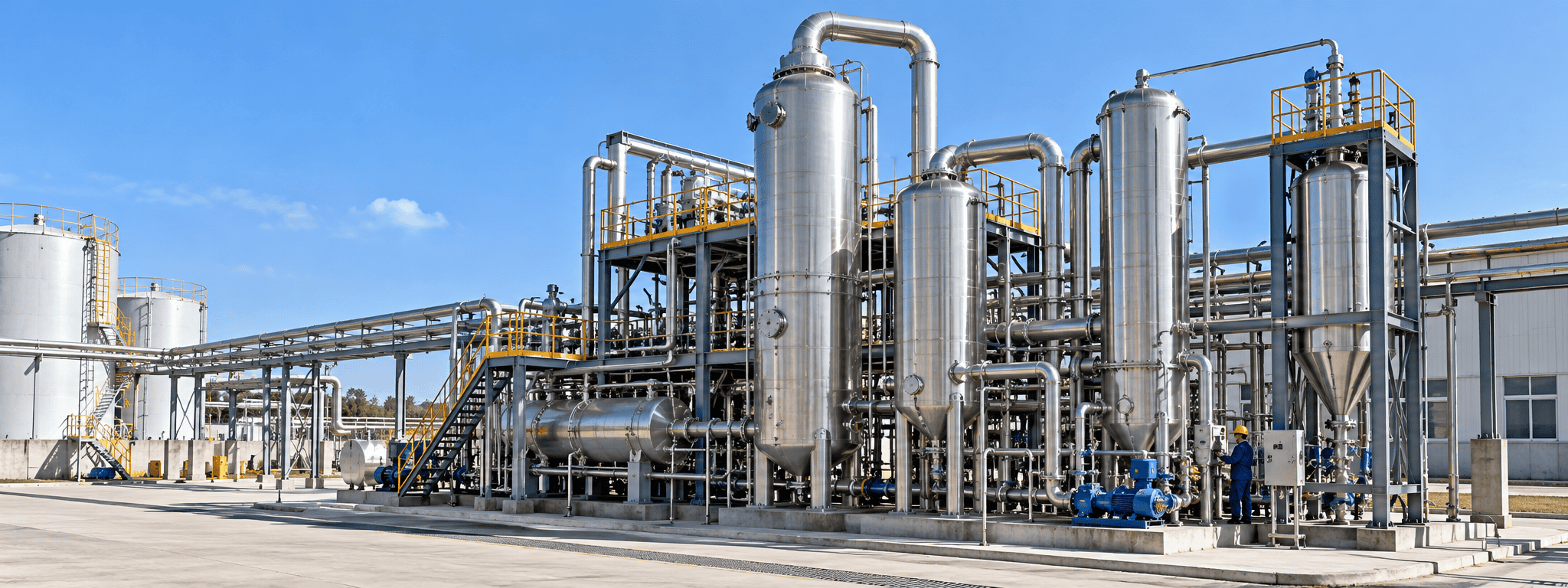
Installed industrial evaporation system operating in a modern process plant environment
Installed Industrial Evaporation System — Application Environment Illustrative application scene. Final equipment arrangement, utilities and site integration depend on the process duty and project layout.
Chemical Processing

Concentrate process solutions or prepare streams for recovery

Review corrosion, boiling-point elevation, precipitation, solvent behavior and the handling of the final concentrate.

Chemical Industry
Water Treatment

Reduce liquid volume and manage concentrated residuals

Review scaling, salts, volatile contaminants, condensate quality and the disposal or downstream treatment route for the remaining concentrate.

Water Treatment
Food & Beverage

Concentrate suitable liquid ingredients or extracts

Review heat sensitivity, residence time, product quality, hygienic design requirements and cleaning conditions.

Food & Beverage Industry
Pharmaceutical Processing

Evaluate defined concentration and recovery duties

Confirm compatibility, containment, cleanability, documentation and any process-specific quality requirements before equipment selection.

Pharmaceutical Industry
Dairy Processing

Concentrate milk- or whey-based process streams

Consider thermal exposure, deposits, product quality, cleaning frequency and the behavior of the stream as solids increase.

Dairy Industry
Brewing & Fermentation

Evaluate fermentation-derived liquids and by-product streams

Review solids, foaming, thermal stability, volatile components and the required quality of recovered water or solvent.

Brewing & Fermentation
How should evaporator capacity be specified?
State feed flow, feed concentration, target concentration and required evaporation separately. If capacity is given in L/h, identify which stream it describes and the density used to convert it to mass flow.
When should falling film be considered?
Falling film is often evaluated for relatively low-viscosity liquids where short thermal exposure and stable film distribution are desirable. Final suitability depends on viscosity, wetting, fouling and the expected concentrate properties.
When is forced circulation more suitable?
Forced circulation is often evaluated when the concentrate becomes more viscous, contains suspended solids, tends to scale or may form crystals. Pump duty and shear sensitivity must also be reviewed.
Does vacuum evaporation automatically reduce energy use?
No. Vacuum lowers boiling temperature, but total purchased energy depends on the heating concept, heat recovery, temperature conditions and auxiliary equipment. Compare steam and electricity on the same evaporation basis.
When should MVR be considered?
MVR should be evaluated where vapor recompression is technically suitable and the operating profile can justify the investment. Compare electricity cost, steam cost, temperature lift, operating hours, load variation, maintenance and supplementary heating requirements.
Can condensate be reused directly?
Only when testing shows that the recovered stream meets the intended reuse requirement. Entrainment and volatile components can affect condensate quality even when droplet separation is effective.
What information is needed for a meaningful quotation?
Begin with feed composition, feed rate, feed concentration, target concentration, temperature limits, operating hours, available utilities and the required supply scope. Mark unknown values instead of treating assumptions as confirmed data.
Share Your Process Data
Turn the process requirement into a project-specific evaporator review
Send your feed composition, flow, concentration target, temperature limits, utilities and available drawings or data sheets. ChannelVessel can use the agreed information to review configuration, materials, utility basis and equipment scope.
Incomplete data is acceptable for an initial inquiry. Mark unknown values clearly so assumptions can be separated from confirmed process conditions.
Scroll to Top
DRAWING & FILE REVIEW

Send Your Drawings

Upload your drawings, datasheets or existing specifications. Our engineering team will review the files and respond with technical feedback.

Engineering Review

Drawings, specifications and process requirements

Confidential File Handling

Project files are used only for technical review and quotation

Faster Technical Feedback

Clearer inputs help us respond more accurately and efficiently

DRAWING & FILE REVIEW

Send Your Drawings

Upload your drawings, datasheets or specifications. Our engineering team will review your files and provide technical feedback.

Contact Form Demo (#3)
Project Protected NDA available
12h Response
ASME / PED
AFTER SUBMISSION
01 Review
→
02 Confirm
→
03 Quote
TECHNICAL QUOTATION

Get a
Technical Quote

Tell us what you need. Our engineering team will review your requirements and respond within 12 hours.

Engineered for Your Application

From concept to certified manufacturing

Global Compliance

ASME, PED and other international standards

Expert Support

Direct access to our engineering team

TECHNICAL QUOTATION

Get a Technical Quote

Tell us what you need. Our engineering team will review your requirements and respond within 12 hours.

Contact Form Demo
Project Protected NDA available
12h Response
ASME / PED
AFTER SUBMISSION
01 Review
→
02 Confirm
→
03 Quote