
Fabrication & Welding for Pressure Vessels
Pressure vessel fabrication depends on more than producing a sound weld. Material control, forming, fit-up, qualified welding procedures, distortion control, inspection and final surface condition all influence whether a vessel can meet its design and service requirements.
Plate preparation, forming, alignment and assembly are managed before welding begins.
Welding procedures, welder qualifications and process parameters are matched to the vessel requirements.
Visual inspection and required NDE are integrated into fabrication rather than left until the end.
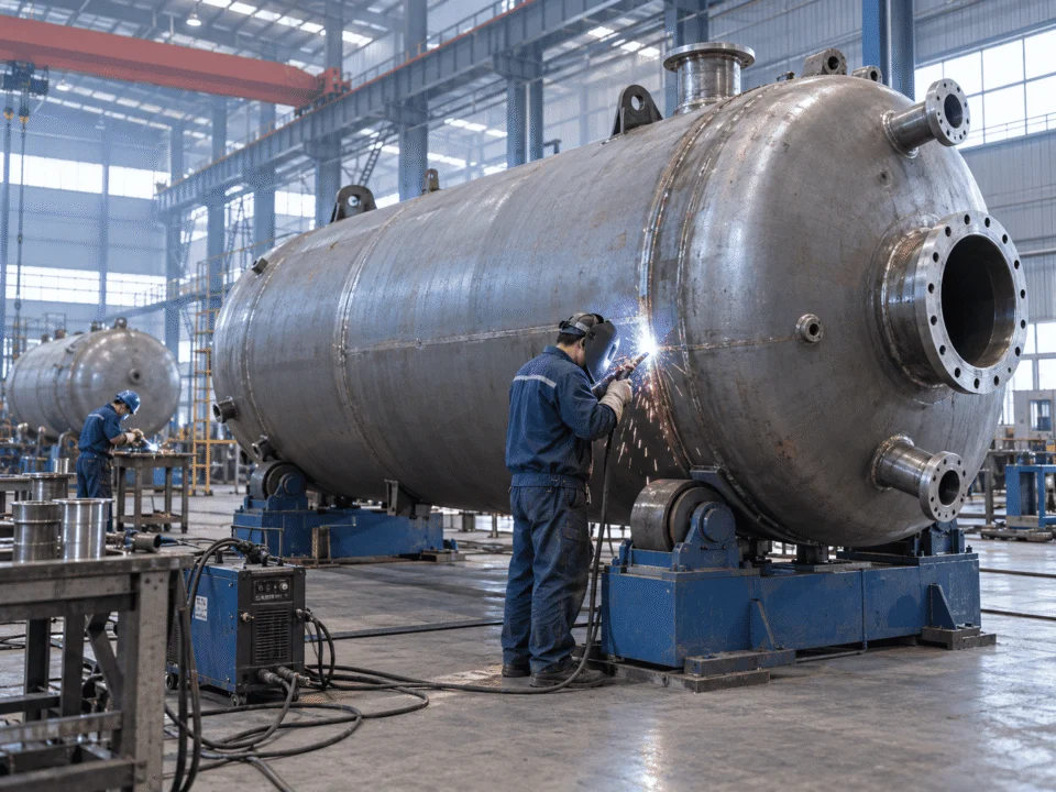
From Plate to Finished Vessel
Pressure vessel fabrication is a controlled sequence. Each stage affects the next, so material identification, forming accuracy, fit-up, welding, inspection and final finishing all need to stay within the project requirements from the start.
Material Receipt & Identification
Plates, forgings, pipes and welding consumables are checked against the required material specification, dimensions and traceability records before fabrication begins.
Cutting, Edge Preparation & Forming
Plate is cut and prepared for welding, then rolled or formed into shells and heads while controlling geometry, edge condition and dimensional accuracy.
Fit-Up & Assembly
Shell courses, heads, nozzles and attachments are aligned and assembled with attention to mismatch, roundness, joint spacing and weld accessibility.
Welding & Process Control
Welding is carried out to approved procedures with control of parameters, consumables, preheat or interpass temperature where required, and sequence to limit distortion.
Inspection, Testing & Final Finish
Required visual and nondestructive examinations are completed during fabrication, followed by dimensional checks, pressure testing where specified, and final surface treatment or cleaning.

Choosing the Right Welding Process
Pressure vessel welding is not based on a single preferred process. The choice depends on joint location, material, thickness, deposition rate, access, heat input and the quality requirements of the finished weld.
A vessel may use more than one welding process within the same fabrication project. For example, a GTAW root pass may be followed by a higher-deposition process for fill and cap passes, while long shell seams may be better suited to automated submerged arc welding.
The correct process is the one that produces the required weld quality efficiently and consistently under the actual fabrication conditions.
| Process | Typical Use | Main Advantage | Key Consideration |
|---|---|---|---|
| GTAW / TIG | Root passes, stainless steel, alloy materials, thin sections and high-cleanliness joints | Excellent arc control and clean, precise weld quality | Lower deposition rate makes it less efficient for large-volume weld metal |
| GMAW / MIG | Production welding, attachments, shell work and applications requiring higher travel speed | Good productivity with continuous wire feeding | Shielding gas coverage, joint cleanliness and parameter control are important |
| SMAW | Manual vessel welding, repair work, restricted access and varied welding positions | Flexible and practical across many workshop conditions | Operator technique, electrode handling and slag removal directly affect consistency |
| SAW | Longitudinal and circumferential seams on thicker shells and large vessels | High deposition rate and strong repeatability for suitable joint geometry | Best suited to accessible, controlled welding positions and longer continuous seams |
Carbon steel, stainless steel and alloy materials may require different consumables, shielding and heat control.
Joint thickness affects bevel design, number of passes, deposition requirement and the practical welding process.
Nozzles, internals and confined vessel geometry can limit torch position, electrode handling and automation options.
Heat input must be managed to support weld quality while controlling distortion and material properties.
Weld Quality Starts Before Welding
A sound pressure vessel weld is not created by arc technique alone. The result depends on how the procedure, welder qualification, joint preparation, consumables and thermal conditions are controlled before and during production.
WPS Defines How the Weld Is Made
The Welding Procedure Specification establishes the essential production variables for the joint, including welding process, base material range, filler metal, joint details, position, electrical parameters and thermal controls where applicable.
PQR Provides Supporting Qualification Data
Procedure Qualification Records document the actual welding variables and test results used to support the qualified welding procedure when qualification is required by the applicable construction code.
Qualified Welders Apply the Procedure
Welder or welding operator qualifications confirm that production personnel are qualified for the applicable process, position, joint type and other required variables within the permitted qualification range.
What Must Stay Under Control
Even a qualified procedure can produce inconsistent results if the fabrication conditions are not controlled on the shop floor.
Bevel angle, root opening, land and surface condition need to match the required joint configuration.
Consumable classification, storage, handling and compatibility with the base material are verified before use.
Where required, minimum preheat is established before welding to manage cooling behavior and cracking risk.
Temperature between weld passes is monitored when limits are important to material properties or procedure compliance.
Current, voltage and travel speed are managed so production remains within the qualified welding range.
Slag, oxide and surface contamination are removed before subsequent passes are deposited.
Material selection, construction code requirements and welding controls need to work together. See our Material Selection and Codes & Standards guidance for the related design and compliance considerations.
Fit-Up, Alignment & Distortion Control
Welding quality depends on the geometry that exists before the arc starts. Shell alignment, joint spacing, roundness and restraint all influence weld consistency, residual stress and the final dimensions of the vessel.

Shell Alignment & Mismatch
Adjacent shell courses and formed components need controlled alignment at the joint. Excessive mismatch can affect weld profile, local stress distribution and inspection results.
Root Gap & Joint Geometry
Root opening, bevel preparation and land dimensions must stay within the intended welding procedure so penetration and weld deposition remain consistent.
Roundness & Dimensional Control
Rolling, forming and assembly can change vessel geometry. Diameter, roundness, straightness and nozzle orientation are checked during fabrication rather than only after final welding.
Welding Sequence & Restraint
Weld sequence, tack weld placement, temporary fixtures and balanced deposition can help reduce distortion while avoiding unnecessary restraint that may increase residual stress.
Correction Before Final Welding
When geometry is outside the required tolerance, correction should be addressed before completing the joint wherever practical rather than relying on post-weld adjustment.
Accurate fit-up supports stable penetration and more uniform weld profiles.
Early correction reduces the risk of cutting, repair welding or dimensional adjustment later.
Controlled geometry makes visual and volumetric examination easier to interpret.
Inspection & NDE of Pressure Vessel Welds
Weld inspection is most effective when it follows the fabrication sequence. Visual examination, surface methods and volumetric methods each answer different questions, and the required combination depends on the joint, material, service condition and applicable construction requirements.
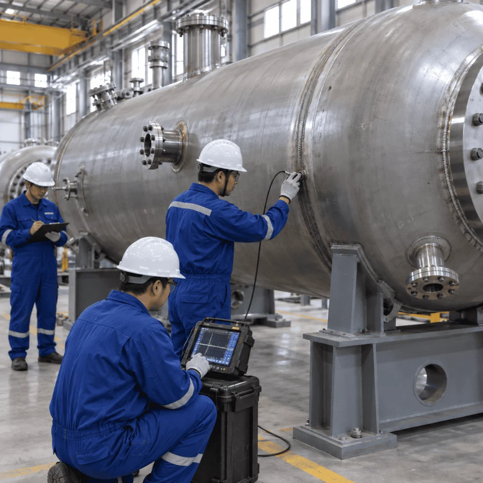
Visual Testing
Visual inspection checks joint preparation, weld profile, surface condition, dimensional features and visible discontinuities before, during and after welding.
Liquid Penetrant Testing
PT is used to reveal surface-breaking discontinuities on nonporous materials and is commonly applied where fine surface defects must be detected.
Magnetic Particle Testing
MT is used on ferromagnetic materials to detect surface and near-surface discontinuities around welds, attachments and other critical areas.
Ultrasonic Testing
UT evaluates internal weld quality using sound waves and can be effective for detecting and locating internal discontinuities in suitable joint geometries.
Radiographic Testing
RT uses X-ray or gamma radiation to produce an image of the weld volume and is widely used for volumetric examination of pressure-retaining joints.
What Each Method Is Best At Finding
No single NDE method is suitable for every discontinuity or every weld. Method selection should match the expected defect type, material and joint geometry.
| Method | Surface Defects | Subsurface / Internal Defects | Typical Pressure Vessel Use |
|---|---|---|---|
| VT | Strong for visible surface conditions | Not intended for internal examination | Fit-up, weld profile, surface condition, dimensional review |
| PT | Very effective for fine surface-breaking indications | No | Stainless steel, nonmagnetic materials, finished weld surfaces |
| MT | Effective for surface and near-surface indications | Limited near-surface capability | Carbon steel welds, attachments and local stress areas |
| UT | Can identify some surface-connected conditions | Strong internal detection capability | Thicker welds, internal discontinuity detection, location and sizing |
| RT | May reveal some surface-connected conditions | Strong volumetric image of weld interior | Pressure-retaining butt welds and code-required volumetric examination |
Inspection points should be planned around the fabrication sequence so critical surfaces and joints remain accessible before later assembly, insulation, lining or additional weld layers make examination more difficult.
See related Codes & Standards guidancePost-Weld Treatment & Surface Condition
Fabrication does not end when welding is complete. Depending on material, thickness, service condition and project requirements, the vessel may require heat treatment, weld finishing, cleaning or surface restoration before final testing and delivery.
Post-Weld Heat Treatment
PWHT may be required to reduce residual stress, control hardness or satisfy material and construction-code requirements. Heating rate, holding temperature, soak time and cooling conditions need to follow the approved procedure.
Weld Grinding & Profile Finishing
Weld reinforcement, transitions and local surface conditions may require controlled grinding where specified. Finishing should improve the required surface condition without reducing material below the permitted thickness.
Pickling & Passivation
Stainless steel fabrication can leave heat tint, embedded contamination and disturbed oxide layers. Pickling and passivation may be used to restore a cleaner, corrosion-resistant surface where the service condition requires it.
Cleaning Before Service
Oil, grease, grinding debris, weld residue and foreign material should be removed to the cleanliness level required by the process service, especially for hygienic, chemical or high-purity applications.
The Required Finish Changes With the Vessel Material
Carbon steel and stainless steel do not receive the same post-weld treatment. The finishing route should match the material and the final operating environment.
Focus is commonly placed on weld cleanup, required PWHT, surface preparation and protective coating systems where corrosion protection is needed.
Carbon Steel Pressure VesselsGreater attention is given to contamination control, heat tint removal, surface restoration, pickling, passivation and cleanliness.
Stainless Steel Pressure VesselsThe final fabrication sequence may include dimensional verification, surface inspection, pressure testing, cleaning and documentation review before the vessel is released for shipment.
Fabrication Requirements Change With Material
The same vessel geometry can require a very different fabrication route when the material changes. Forming behavior, welding consumables, heat input, contamination control, preheat, post-weld treatment and surface protection all depend on the selected material system.
Robust Fabrication With Thermal Control
Carbon steel is widely used for pressure vessels because of its availability, strength and fabrication practicality, but welding conditions still need to reflect thickness, carbon equivalent, restraint and service requirements.
May be required to reduce hydrogen-assisted cracking risk in thicker or higher-strength joints.
Filler metal selection must match the required mechanical properties and applicable procedure.
Blasting, coating or other protection may be needed when corrosion resistance is not provided by the base metal itself.
Clean Fabrication & Contamination Control
Stainless steel fabrication requires tighter control of cleanliness and contact with carbon steel tooling because surface contamination can reduce corrosion performance even when the weld itself is sound.
Grinding wheels, brushes and handling equipment should avoid transferring carbon steel contamination.
Welding and purge conditions influence oxidation around the joint and may affect later cleaning requirements.
Pickling, passivation or other finishing may be specified to restore the required corrosion-resistant surface.
Procedure Discipline Becomes More Critical
Alloy steels can require narrower control of welding parameters because heat treatment response, hardness and metallurgical behavior may be more sensitive than standard carbon steel.
Welding energy must remain within the qualified range to protect the required material properties.
Preheat and interpass temperature can become essential production controls.
Post-weld heat treatment may be required to achieve the intended hardness, toughness or stress condition.
Protect the Corrosion-Resistant Layer
Clad plate and lined vessels combine structural and corrosion-resistant materials, so fabrication must consider both the load-bearing base material and the integrity of the protective layer.
Machining and beveling must preserve the intended relationship between base metal and corrosion-resistant layer.
Base-metal welding and overlay or lining restoration need to follow the approved sequence.
The corrosion barrier must remain continuous after welding, grinding and inspection.
Material Selection Changes the Entire Fabrication Plan
Material choice affects forming, welding process selection, consumables, heat treatment, cleaning, inspection and final surface condition. It should therefore be reviewed before fabrication planning is finalized.
What We Review Before Fabrication Starts
Fabrication should not begin until the vessel requirements are clear enough for engineering, purchasing, welding and inspection teams to work from the same basis. A structured review reduces late changes, rework and unnecessary production delays.
Design Conditions
Design pressure, design temperature, operating conditions, corrosion allowance, vacuum requirements and other service inputs are checked against the vessel design basis.
Approved Drawings
General arrangement drawings, nozzle orientation, supports, internals, weld details and dimensional requirements need to be sufficiently defined before shop release.
Material Requirements
Plate, pipe, forgings, flanges, fittings, bolts and welding consumables are reviewed for specification, grade, thickness and traceability requirements.
Welding Requirements
Applicable welding procedures, joint details, consumables, preheat, interpass limits, purge requirements and any special welding restrictions are identified before production.
NDE & Inspection Plan
Required VT, PT, MT, UT, RT, hold points and inspection stages are planned so critical joints remain accessible at the correct stage of fabrication.
Heat Treatment
Where PWHT or other thermal treatment is required, the temperature range, sequence, equipment, monitoring and documentation requirements are reviewed in advance.
Surface Condition
Grinding, blasting, coating, pickling, passivation, polishing or cleanliness requirements are confirmed so the fabrication route supports the final service condition.
Documentation
Material certificates, weld records, NDE reports, heat-treatment charts, dimensional records and final manufacturing documentation are defined before release to production.
Resolve the Critical Inputs Before Metal Is Cut
Late design changes become more expensive once material is ordered, plate is formed or pressure-retaining welds are completed. Early review keeps fabrication aligned with the final vessel requirement.
Send them for an initial fabrication review before production planning starts.
Send Your DrawingsCommon Questions About Pressure Vessel Fabrication & Welding
These questions cover some of the most common technical issues that affect pressure vessel welding, inspection, heat treatment and fabrication planning.
A WPS, or Welding Procedure Specification, defines how production welding should be performed. A PQR, or Procedure Qualification Record, documents the actual welding variables and test results used to support qualification of the procedure where required by the applicable construction code.
There is no single best welding process for every vessel. GTAW is often selected for precise root welding or stainless steel, SAW for long heavy-section seams, GMAW for productive shop welding, and SMAW where flexibility or access is important. A single vessel may use several processes.
PWHT requirements depend on factors such as material type, thickness, joint category, service condition and the applicable construction code. It may be used to reduce residual stress, control hardness or achieve required material properties.
Fit-up controls alignment, root gap, mismatch, roundness and joint geometry before welding. Poor fit-up can make penetration less consistent, increase distortion, complicate inspection and create dimensional problems later in fabrication.
Distortion can be reduced through accurate fit-up, balanced welding sequences, controlled heat input, suitable tack welding, temporary fixtures and planned weld progression. Dimensional checks during fabrication help identify movement before it becomes difficult to correct.
Common methods include visual testing, liquid penetrant testing, magnetic particle testing, ultrasonic testing and radiographic testing. The required method depends on the material, weld type, expected discontinuities and construction requirements.
Carbon steel particles transferred by grinding wheels, brushes, handling equipment or nearby fabrication work can contaminate stainless steel surfaces and reduce corrosion performance. Dedicated or properly controlled tools and work practices help prevent this contamination.
No. Inspection should be integrated into the fabrication sequence. Joint preparation, fit-up, root passes, intermediate weld stages and completed welds may all require inspection before later work makes the area inaccessible.
Useful inputs include design pressure and temperature, material requirements, vessel drawings, nozzle orientation, welding requirements, NDE scope, heat-treatment requirements, surface finish, process service and required manufacturing documentation.