
ChannelVessel Intelligent Equipment Co., Ltd. Contact Us
Stainless Steel Heat Exchangers

Stainless Steel Heat Exchangers Engineered Around the Process

Custom heat exchangers designed around heat duty, fluid properties, allowable pressure drop, fouling behavior and corrosion conditions—not simply a requested surface area.

Materials 304 / 316 / 316L & project-specific alloys
Engineering Input Media, flow, temperature, pressure & cleaning
Configuration Custom tube layout, bundle, connections & finish

You do not need to know the required heat-transfer area before contacting us. Send the operating conditions you already have and we can identify the remaining design inputs.
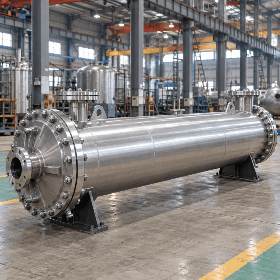
Stainless steel shell and tube heat exchanger in a Chinese manufacturing facility
Process In Media · Flow · Temperature · Pressure
Engineering Out Duty · ΔP · Area · Material · Geometry
PERFORMANCE LOGIC

What Actually Determines Heat Exchanger Performance?

Surface area is only one part of the answer.

Heat exchanger sizing begins with thermal duty, but the final design also depends on temperature driving force, fluid velocity, allowable pressure drop and fouling behavior. These variables work together, so optimizing one in isolation can create problems somewhere else.

THERMAL RELATIONSHIP
Q = U × A × ΔTlm

Required heat-transfer area depends on the thermal duty, overall heat-transfer coefficient and usable temperature difference.

Q

Heat Duty

The process determines how much heat must be transferred.

ΔT

Temperature Driving Force

The usable temperature difference determines how much area is needed.

›

Fluid Velocity

Velocity changes turbulence, heat transfer and deposit behavior.

DESIGN TARGET

Balanced Thermal
+ Hydraulic
Performance

Not maximum area. Not maximum velocity. Not minimum pressure drop.

↯

Pressure Drop

Higher velocity may improve heat transfer, but hydraulic cost rises too.

≡

Fouling

Deposits add thermal resistance and can change long-term performance.

WHY THIS MATTERS

The best exchanger is not the one with the largest heat-transfer area.

It is the one that reaches the required process temperatures without creating unnecessary pressure drop, pumping demand, fouling risk or cleaning difficulty.

WHAT WE CALCULATE From your process data
Heat duty
Temperature driving force
Required heat-transfer area
Tube / shell velocity
Expected pressure drop
Fouling allowance
Material compatibility
Cleaning requirements
MATERIAL SELECTION

304 vs 316L — And When Neither Is Enough

Stainless steel selection starts with the fluid, not the grade name.

304 and 316L are both widely used in process equipment, but the correct choice depends on the actual service environment. Chlorides, operating temperature, pH, oxidizing conditions, cleaning chemicals and stagnant areas can all change corrosion behavior.

WHY THIS MATTERS

316L is not automatically corrosion-proof.

High chloride exposure, elevated temperature, aggressive cleaning chemistry or unfavorable geometry can still create localized corrosion risks.

What changes the material decision? Process environment
Chloride concentration
Operating temperature
pH & oxidizing conditions
Cleaning chemicals
Crevices & stagnant zones
Product contamination limits
304

General Process Service

A practical option for many water, utility and relatively mild process environments where additional corrosion resistance is not required.

Typical decision driver Mild chemistry + controlled operating conditions
BEYOND

When 316L Is Not Enough

For more aggressive service, increasing wall thickness is not always the right answer. The material system itself may need to be reconsidered.

Possible alternatives Higher-alloy stainless, duplex, titanium or other corrosion-resistant materials
→
Material selection rule Choose from the actual fluid chemistry and operating temperature — not simply “304 or 316L.”
PROCESS DATA

Give Us the Process Data — We Size the Exchanger

You do not need to know the required heat-transfer area before requesting a quote.

The useful starting point is the process itself: what is being heated or cooled, how much is flowing, where the temperatures begin and where they need to end.

HOT SIDE

Process Stream A

Required Inputs
Medium What fluid enters the exchanger?
Flow Rate Mass flow or volumetric flow
Inlet Temperature Normal operating condition
Required Outlet Temperature The process target
HEAT DUTY Process In Design Out
COLD SIDE

Process Stream B

Required Inputs
Medium What fluid receives the heat?
Flow Rate Mass flow or volumetric flow
Inlet Temperature Available utility condition
Required Outlet Temperature Expected thermal result
Stainless steel heat exchanger in manufacturing workshop
ADDITIONAL DESIGN INPUTS These can change the final configuration
Operating pressure
Design pressure
Maximum allowable pressure drop
Fluid composition
Density & viscosity
Solids / suspended particles
Fouling or crystallization tendency
Phase change, if applicable
Steam / utility conditions
Cleaning method
Connection standard
Preferred material
INCOMPLETE DATA?

Send what you already know.

We can identify which missing inputs are required before the exchanger configuration is finalized. For processes with a wide operating range, minimum and maximum flow conditions may also matter.

01 Process conditions
→
02 Engineering review
→
03 Exchanger configuration
Send Process Data
FLOW GEOMETRY

Tube Layout, Velocity & Pressure Drop

Internal geometry changes how the exchanger operates.

Tube diameter, pitch, arrangement and baffle configuration influence both thermal and hydraulic performance. The design target is not maximum velocity or minimum pressure drop—it is a practical operating balance.

TUBE ARRANGEMENT Geometry changes flow behavior
TRIANGULAR PITCH

Compact Packing + Stronger Flow Interaction

A triangular arrangement can place more tubes into a given shell diameter and can increase shell-side turbulence where compact thermal performance matters.

Dense tube packing Higher shell-side interaction Less direct mechanical cleaning access
SQUARE PITCH

Clearer Paths + Better Mechanical Access

A square arrangement provides straighter paths between tubes and can be preferable when shell-side mechanical cleaning or deposit removal is important.

Clearer cleaning lanes Useful for fouling-sensitive service Different shell-side flow behavior
VELOCITY WINDOW Control it—do not maximize it
TOO LOW Lower transfer
Higher deposit risk
DESIGN RANGE Balanced thermal + hydraulic performance
TOO HIGH Higher ΔP
More pumping demand
WHAT CHANGES WHEN VELOCITY RISES?
Heat transfer
→
Often improves
Turbulence
→
Usually increases
Pressure drop
→
Also increases
Pumping demand
→
Can increase
DESIGN RULE

Enough velocity for effective heat transfer—without creating unnecessary pressure drop.

Tube Diameter Changes velocity and available flow area
Tube Pitch Changes packing density and shell-side flow
Baffle Configuration Changes cross-flow, turbulence and ΔP
Cleaning Requirement Changes which geometry is practical
FOULING BEHAVIOR

Fouling Is a Design Input

The exchanger must still perform after it has been operating.

A heat exchanger may perform well when completely clean and gradually lose efficiency as deposits build on the heat-transfer surface. Fouling therefore needs to be considered together with velocity, pressure drop, surface area and cleaning strategy.

PERFORMANCE THROUGH THE SERVICE CYCLE Clean condition → operating condition → cleaning decision
CLEAN SURFACE

Low added thermal resistance

The exchanger begins with the intended heat-transfer surface condition and design flow paths.

DEPOSIT FORMATION

Scale, solids or product films begin to build

Deposits add resistance between the process fluid and the heat-transfer surface, reducing effective heat transfer.

OPERATING IMPACT

Thermal performance can drift away from the clean condition

The required outlet temperature may become harder to maintain, while hydraulic behavior can also change as deposits alter the flow passages.

ENGINEERING RESPONSE

Balance fouling allowance with velocity, area and cleanability

The goal is a design that remains practical to operate and clean—not simply one that has the largest possible heat-transfer area.

COMMON FOULING MECHANISMS Different deposits need different design responses
Mineral scale
Suspended solids
Crystallization
Polymer or product deposits
Biological deposits
High-viscosity films
DESIGN BALANCE Flow Velocity + Pressure Drop + Surface Area + Fluid Behavior + Cleaning Method
STREAM ALLOCATION

Which Fluid Should Go on the Tube Side?

Side allocation should follow the process—not a default hot-side / cold-side rule.

Pressure, corrosion, fouling, viscosity, cleanability and phase behavior can all affect whether a stream is better suited to the tube side or shell side.

ENGINEERING QUESTION What is the dominant constraint?
PRESSURE

Higher-pressure service

Tube-side placement may be advantageous in some applications because the smaller containment diameter can simplify the mechanical pressure boundary.

Often evaluated toward Tube Side
FOULING

Deposit-forming service

The preferred side depends on where deposits are likely to form and which surfaces must remain accessible for inspection or mechanical cleaning.

Decision depends on Cleaning Strategy
CORROSION

Corrosive process fluid

Stream allocation can affect how much corrosion-resistant material is exposed and which components must be upgraded to a higher-alloy material.

Decision depends on Material Exposure
VISCOSITY

High-viscosity fluid

Available flow area, achievable velocity and allowable pressure drop need to be checked together before deciding which side is more practical.

Decision depends on Hydraulic Behavior
PHASE CHANGE

Condensing or evaporating service

Phase change introduces flow-distribution, pressure-drop and drainage considerations that can strongly influence stream placement.

Decision depends on Distribution + Drainage
TUBE SIDE

Useful when containment, cleaning access or controlled velocity drives the decision.

Smaller pressure boundary diameter Defined internal flow path Can support direct tube cleaning access
NO DEFAULT Hot ≠ automatically shell side Cold ≠ automatically tube side
SHELL SIDE

Useful when shell-side geometry better supports the required flow distribution or phase behavior.

Cross-flow around tube bundle Can suit selected phase-change duties Baffle design changes velocity and ΔP
DESIGN RULE

Tube-side and shell-side allocation is part of the exchanger design—not a catalogue default.

The correct choice is made after the process constraints are understood together.

CONSTRUCTION DETAILS

Construction Details That Affect Service Life

The stainless steel grade is only one part of the equipment.

A heat exchanger can be specified as 316L and still contain local areas that experience very different corrosion, cleaning and mechanical conditions. Service life depends on how the entire exchanger is detailed and fabricated around the material choice.

Tube-to-tubesheet joint
Welded area
Crevice zone
Nozzle transition
LOCAL CONDITIONS MATTER Bulk-fluid chemistry does not tell the whole corrosion story.
A
TUBE-TO-TUBESHEET JOINTS

Sealing, geometry and fabrication quality all matter

This interface affects mechanical integrity, leakage control and the local environment around the joint.

B
WELDED AREAS

Heat input and finishing influence the final surface condition

Welding procedure, heat-affected zones and subsequent treatment can change corrosion behavior and cleanability.

C
CREVICES

Stagnant gaps can create a different local environment

Narrow gaps may concentrate chemistry and retain liquid even when the bulk process fluid appears acceptable.

D
NOZZLES & TRANSITIONS

Flow geometry should support drainage and avoid unnecessary hold-up

Connection geometry, internal transitions and drain paths matter especially where cleaning or batch changeover is frequent.

SURFACE TREATMENT Specified according to material and service
Pickling
Passivation
Polishing
Drainability review
DESIGN RULE

Choosing the correct alloy matters. Fabricating the exchanger correctly around that alloy matters just as much.

CLEANABILITY & SANITARY OPTIONS

Heat Transfer Must Work Between Cleaning Cycles Too

A polished surface alone does not automatically make an exchanger easy to clean.

For food, beverage, dairy and pharmaceutical processes, cleanability depends on surface condition, drainage, flow path, connection geometry and the cleaning method available at the plant.

A
PROCESS RUN

Product flows through the exchanger

Thermal performance, residence behavior and product contact surfaces all matter during production.

→
B
DRAINAGE

Residual liquid should not be trapped unnecessarily

Geometry and orientation should support practical draining where the process requires it.

→
C
CLEANING CYCLE

CIP flow needs a practical path

Cleaning effectiveness depends on circulation, velocity, access and how the internal geometry is arranged.

→
D
RETURN TO SERVICE

The exchanger should be ready for repeatable operation

Cleanability and thermal duty need to work together over repeated production cycles.

DESIGN CHECKS What should be reviewed for hygienic or frequent-cleaning service?
INTERNAL SURFACE FINISH Specified according to process and hygiene requirements.
DRAINABILITY Reduce unnecessary retained liquid where required.
CIP COMPATIBILITY Cleaning flow paths should be considered during design.
STAGNANT-ZONE REDUCTION Review internal geometry and connection details.
HYGIENIC CONNECTIONS Available where sanitary piping systems are required.
SERVICE ACCESS Accessible or removable construction can be considered where needed.
KEY POINT

Surface finish, drainage, flow path and cleaning method must work together.

Cleanability is part of process design—not a finishing step added after the exchanger geometry has already been fixed.

SIMPLE SELECTION EXAMPLE

Start With the Duty, Not the Exchanger Size

A target temperature tells us the objective—but not yet the exchanger geometry.

This simplified example shows why a request should begin with process conditions instead of an arbitrary heat-transfer area.

PROCESS LIQUID
80°C → 40°C

Required cooling target

KNOWN CONDITION This defines the thermal objective. NOT YET KNOWN This does not define the exchanger size.
COOLING WATER
25°C → ?

Outlet condition still needs to be established
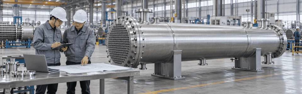
Engineering review of a stainless steel heat exchanger in the manufacturing workshop
WHAT ELSE DO WE NEED? The missing inputs determine how the exchanger is configured
Process flow rate
Available cooling-water flow
Acceptable utility outlet temperature
Allowable pressure drop on each side
Fluid viscosity
Solids or fouling tendency
Material compatibility
Cleaning method
DESIGN SEQUENCE What gets decided first, and what follows from it?
Process Duty

How much heat must be removed or added?

Fluid Properties

How do viscosity, density and composition affect flow and transfer?

Temperature Driving Force

How much usable temperature difference is available?

Pressure Drop

How much hydraulic resistance can the process tolerate?

Fouling

How will deposits affect operation and cleaning?

Material

What alloy is compatible with the process environment?

Geometry

Only then should area, tube layout and internal configuration be fixed.

THE WRONG STARTING POINT “Build me a 20 m² exchanger.”
THE BETTER STARTING POINT “Here are my media, flow rates, temperatures, pressure limits and cleaning requirements.”
CONFIGURED AROUND THE APPLICATION

Typical Stainless Steel Heat Exchanger Options

The final specification should match the real operating envelope—not a catalogue template.

ChannelVessel can configure stainless steel heat exchangers around thermal duty, hydraulic limits, maintenance strategy, piping requirements and material compatibility.

CONFIGURATION PRINCIPLE Do not maximize every specification.

The largest area, thickest wall and highest nominal rating do not automatically produce the best exchanger. Each choice should solve a real process requirement.

MATERIALS

304 / 316 / 316L Stainless Steel

Alternative materials can be evaluated where the process chemistry requires a different corrosion-resistant solution.

Selected from media + temperature + cleaning chemistry
TUBE CONFIGURATION

Diameter, Wall Thickness, Pitch & Arrangement

These choices influence heat-transfer area, fluid velocity, pressure drop, fouling tendency and cleaning access.

Thermal + hydraulic decision
BUNDLE CONFIGURATION

Fixed or Serviceable Construction

The maintenance strategy can influence whether direct inspection, removal or mechanical cleaning access is needed.

Maintenance strategy matters
BAFFLE CONFIGURATION

Shell-Side Flow Distribution & Pressure Drop

Baffle arrangement affects cross-flow, turbulence, unsupported tube length and shell-side hydraulic behavior.

Balance transfer with ΔP
CONNECTIONS

Flanged, Threaded or Hygienic Connections

Connection type and orientation should match the plant piping, process requirements and cleaning strategy.

Match the surrounding process system
SURFACE TREATMENT

Pickling, Passivation & Polishing Options

Surface treatment can be specified according to stainless steel grade, corrosion environment, hygienic requirements and product-contact expectations.

Specified by service—not appearance
ORIENTATION

Horizontal or Vertical Arrangement

Installation orientation can be reviewed around process behavior, available space, drainage, maintenance and nozzle routing.

Plant layout + process behavior
WHAT SHOULD DRIVE THE FINAL SPECIFICATION? Use the operating conditions to justify every configuration choice.
Heat duty
Allowable pressure drop
Corrosion environment
Fouling tendency
Cleaning method
Maintenance access
Piping standard
Installation constraints
APPLICATIONS

Stainless Steel Heat Exchangers for Different Processes

The same stainless steel exchanger should not be applied unchanged across every industry.

What matters most changes with the process: corrosion in chemical service, cleanability in pharmaceutical production, product fouling in dairy, or repeatable temperature control in brewing and food processing.

THE INDUSTRY NAME IS NOT THE DESIGN BASIS Media, flow rate, temperatures, pressure, fouling behavior and cleaning requirements still determine the exchanger configuration.
READY TO SIZE YOUR EXCHANGER?

Send the Process, Not Just a Size

You do not need to select every construction detail before contacting us.

Send the process information you already have. ChannelVessel can review the heat duty, material selection, pressure-drop requirements and exchanger configuration before quotation.

USEFUL STARTING DATA Even partial information is enough to begin
Media Hot side + cold side
Flow Rates Mass or volumetric flow
Temperatures Inlet + target outlet
Pressure Operating + design if known
Cleaning Requirements CIP / manual / mechanical access
DON'T HAVE EVERYTHING? Send what you know. We can identify the missing design inputs before the exchanger is configured.
ENGINEERING FAQ

Common Questions Before Specifying a Stainless Steel Heat Exchanger

Useful answers should reduce uncertainty before quotation—not just repeat catalogue claims.

QUICK START

You do not need a finished exchanger specification to begin.

Media, flow rates, inlet and outlet temperatures, pressure limits and cleaning requirements are usually the most useful starting inputs.

Is 316L always the best stainless steel for a heat exchanger? +

No. 316L is widely used, but material selection still depends on chloride concentration, operating temperature, pH, cleaning chemistry, stagnant areas and the actual process fluid. More aggressive service may require a different alloy system.

Do I need to know the required heat-transfer area before requesting a quote? +

Not necessarily. Heat-transfer area should normally be calculated from the thermal duty, fluid properties, temperature driving force, allowable pressure drop and fouling assumptions rather than chosen first.

Why not simply choose a larger exchanger for extra safety margin? +

Additional area can be useful, but excessive oversizing can also reduce operating velocity in some services. Lower velocity may reduce heat transfer and can make certain fouling mechanisms harder to control.

How much pressure drop should a heat exchanger have? +

There is no single value that fits every process. The allowable pressure drop should come from the surrounding system, pump capability, utility conditions and process constraints. It must be balanced against velocity and thermal performance.

Should the hot fluid always go on the shell side? +

No. Tube-side and shell-side allocation can depend on pressure, corrosion, fouling, viscosity, cleanability, phase change and material cost. Stream placement is part of the exchanger design.

When is square tube pitch preferable to triangular pitch? +

Square pitch can be useful when clearer mechanical cleaning paths are important. Triangular arrangements can provide denser packing and stronger shell-side flow interaction. The choice depends on thermal duty, fouling and cleaning requirements.

Can a stainless steel heat exchanger be designed for CIP cleaning? +

Yes, where the process requires it. CIP compatibility should be considered together with drainage, internal geometry, stagnant-zone reduction, surface condition and hygienic connection requirements.

What information is most useful for sizing an exchanger? +

Start with the hot-side and cold-side media, flow rates, inlet temperatures, required outlet temperatures, operating pressure, allowable pressure drop, fluid properties, fouling tendency and cleaning method. Partial information is still useful.

Scroll to Top
DRAWING & FILE REVIEW

Send Your Drawings

Upload your drawings, datasheets or existing specifications. Our engineering team will review the files and respond with technical feedback.

Engineering Review

Drawings, specifications and process requirements

Confidential File Handling

Project files are used only for technical review and quotation

Faster Technical Feedback

Clearer inputs help us respond more accurately and efficiently

DRAWING & FILE REVIEW

Send Your Drawings

Upload your drawings, datasheets or specifications. Our engineering team will review your files and provide technical feedback.

Contact Form Demo (#3)
Project Protected NDA available
12h Response
ASME / PED
AFTER SUBMISSION
01 Review
→
02 Confirm
→
03 Quote
TECHNICAL QUOTATION

Get a
Technical Quote

Tell us what you need. Our engineering team will review your requirements and respond within 12 hours.

Engineered for Your Application

From concept to certified manufacturing

Global Compliance

ASME, PED and other international standards

Expert Support

Direct access to our engineering team

TECHNICAL QUOTATION

Get a Technical Quote

Tell us what you need. Our engineering team will review your requirements and respond within 12 hours.

Contact Form Demo
Project Protected NDA available
12h Response
ASME / PED
AFTER SUBMISSION
01 Review
→
02 Confirm
→
03 Quote