
ChannelVessel Intelligent Equipment Co., Ltd. Contact Us
ENGINEERED AGITATED REACTORS

Agitated Reactors Engineered Around Your Mixing Duty

Custom reactor vessels designed around viscosity, solids loading, heat-transfer duty, pressure, temperature and required mixing performance—not vessel volume alone.

Mixing system selected around the actual process objective

Agitator, vessel, seal and heat-transfer system engineered together

Configurable materials, internals, jacket options and control system

For a faster engineering review, include working volume, viscosity range, operating pressure, operating temperature and mixing duty.

Agitated reactor
Mixing First Duty-based configuration
Integrated Design Vessel + agitator + thermal system
SYSTEM INTEGRATION

An Agitated Reactor Is Three Engineered Systems Working as One

The vessel, agitation system and heat-transfer system should be designed together. Changing one can affect mixing performance, thermal response, shaft loading, seal duty and overall process reliability.

VESSEL SYSTEM

The vessel defines the physical environment for the reaction.

Diameter, straight-side height, working volume, head geometry, nozzle arrangement and internal clearances influence circulation patterns, usable batch volume and agitator geometry.

Geometry Diameter-to-height ratio and liquid level affect circulation.
Pressure & Temperature Shell, heads, nozzles and supports are engineered around the design condition.
Internals Baffles, dip pipes, coils and instruments must not interfere with the mixing zone.
Explore Reactor Vessels →
AGITATION SYSTEM

The agitator should be selected from the process duty—not from RPM alone.

Impeller type, diameter, shaft length, speed, torque and motor power should respond to viscosity, density, solids content, gas dispersion needs and the required flow pattern.

Flow Pattern Axial, radial or tangential flow changes how material moves through the vessel.
Torque High-viscosity service can be torque-limited even when rotational speed is low.
Shaft & Seal Mechanical loading and sealing duty should be checked together with the process condition.
Compare Mixing Tanks →
HEAT-TRANSFER SYSTEM

Mixing directly affects how efficiently heat reaches the process fluid.

Jacket area alone does not define thermal performance. Wall-side velocity, viscosity, impeller selection and the location of coils or baffles can all change heat-transfer behavior.
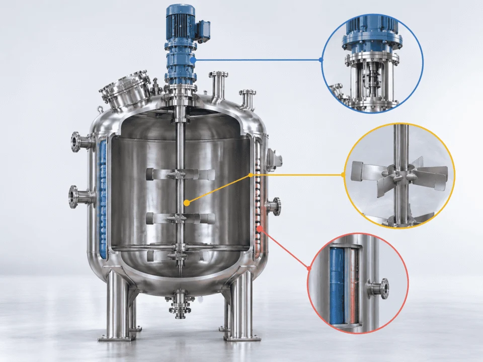
Jacket Duty Heating or cooling load should be matched to the required batch response.
Wall Circulation Good fluid movement near the wall helps reduce thermal gradients.
Integration Jacket, coil and agitator geometry should be checked as one system.
Explore Jacketed Reactors →
Agitated reactor technical structure
The design target is process performance.

Mixing uniformity, suspension, heat transfer and equipment reliability should be evaluated together.

Mixing Uniformity
Solids Suspension
Thermal Response
Mechanical Reliability
START WITH THE PROCESS DUTY

Choose the Mixing Duty Before You Choose the Impeller

The same reactor volume can require a completely different agitation system depending on viscosity, solids, gas introduction, heat-transfer demand and shear sensitivity. Start with what the process needs to achieve.

LIQUID BLENDING

Focus on circulation and blend time.

Mixing duty first

Low- to medium-viscosity liquid blending is usually governed by how quickly the agitator can circulate the vessel contents and eliminate concentration gradients.

Primary design focus Axial circulation
Check first Viscosity + density
Watch for Dead zones
Common impeller family PBT / hydrofoil
Blend time Impeller diameter Power per volume Liquid level
SOLIDS SUSPENSION

Design around particle behavior, not just RPM.

Suspension duty

Solids suspension depends on particle size, density difference, solids concentration, liquid viscosity and how close the impeller operates to the vessel bottom.

Primary design focus Bottom-to-top circulation
Check first Particle size + solids %
Watch for Settling zones
Common impeller family PBT / hydrofoil
Settling tendency Off-bottom clearance Batch level Torque
GAS DISPERSION

Gas rate can change the entire agitation requirement.

Gas-liquid duty

Gas-liquid service needs enough local energy to break and redistribute bubbles while maintaining bulk circulation through the vessel.

Primary design focus Bubble dispersion
Check first Gas rate + liquid depth
Watch for Flooding / poor dispersion
Common impeller family Radial / suitable turbine
Gas flow Impeller spacing Power under gassing Baffles
HIGH VISCOSITY

Low speed can still mean very high torque.

Torque-driven duty

High-viscosity processes are often governed by torque, wall clearance and bulk movement rather than by high rotational speed. Viscosity changes during the batch should be considered.

Primary design focus Bulk turnover
Check first Max viscosity in batch
Watch for Stagnant wall zones
Common impeller family Anchor / helical
Torque Wall clearance Viscosity curve Shaft loading
HEAT TRANSFER

Wall circulation matters as much as jacket area.

Thermal duty

When heating or cooling is the critical process objective, the agitator should keep fluid moving through the wall region and reduce temperature gradients throughout the batch.

Primary design focus Wall-side circulation
Check first Thermal duty + viscosity
Watch for Hot / cold spots
Common impeller family PBT / anchor
Heating duty Cooling duty Wall velocity Batch time
SHEAR-SENSITIVE PROCESS

More speed is not always better mixing.

Controlled shear

Fragile crystals, biological materials or shear-sensitive formulations may require lower local shear while still maintaining enough circulation for uniform processing.

Primary design focus Gentle circulation
Check first Shear sensitivity
Watch for Product damage
Common impeller family Low-shear axial flow
Tip speed Crystal integrity Blend time Impeller geometry
Why this matters

Two reactors with the same working volume can require different impellers, shaft sizes, motor power and seals when the process duty changes.

AGITATOR CONFIGURATIONS

Impeller Type Is Only One Part of the Mixing System

Impeller geometry should be selected together with shaft length, diameter, speed, number of stages, baffle arrangement and the process condition across the full batch.

Agitated reactor internal agitator configuration

For tall vessels or wide operating levels, one impeller stage may not provide enough circulation through the full liquid column.

Configuration Typical Duty Flow Character Key Check
A Hydrofoil
Liquid blending, suspension High axial flow Circulation efficiency
B Pitched Blade Turbine
General mixing, solids Axial / mixed flow Blade angle + clearance
C Rushton Turbine
Gas-liquid dispersion Strong radial flow Power under gassing
D Anchor
High-viscosity service Wall-following flow Torque + wall clearance
E Paddle
Gentle bulk mixing Broad circulation Dead-zone control
F Helical / Ribbon
Very high viscosity Axial turnover Shaft load + torque
ENGINEERING CHECK

Do not size the agitator from RPM alone.

Impeller Diameter Relative to vessel diameter
Tip Speed Related to shear and dispersion
Torque Critical for viscous service
Stage Spacing Important in tall vessels
One impeller is not always enough

Tall liquid columns may need multiple stages to maintain circulation through the full vessel.

Baffles change the flow pattern

Baffle design can suppress vortexing and redirect rotational flow into useful circulation.

Batch conditions can change

Initial, maximum and final viscosity may require the drive system to handle very different loads.

FROM PROCESS DATA TO EQUIPMENT DESIGN

Agitator Sizing Starts With Process Data, Not a Motor Catalog

A reliable agitator configuration is built by translating process conditions into hydraulic and mechanical requirements, then checking the vessel, shaft, drive and seal as one system.

INPUT
Process Data What we need from the application
Viscosity Initial · peak · final
Density Liquid and suspended phases
Solids Loading · size · settling behavior
Gas Flow rate and dispersion duty
Working Level Minimum and maximum batch level
Temperature Operating range and thermal duty
ENGINEERING
CHECK
Engineering Evaluation What changes the mechanical design

Flow regime
Whether the batch behaves as low-, transitional- or high-viscosity mixing.

Power demand
How much energy is required to create useful circulation.

Torque demand
Especially important when viscosity rises during reaction.

Tip speed
Checked against shear, dispersion and product sensitivity.

Shaft loading
Bending, torsion and unsupported shaft length matter.

Critical speed
Operating speed should avoid problematic vibration ranges.

OUTPUT
DESIGN
Agitator Configuration What the process data finally controls
Impeller Type
Impeller Diameter
Impeller Stages
Agitator RPM
Drive Motor Power
Drive Gear Ratio
Shaft Diameter
Seal Configuration
SAME VESSEL VOLUME. DIFFERENT AGITATOR.

5,000 L does not tell you how to mix the batch.

PROCESS A Low-viscosity blending
Viscosity Low
Main objective Fast circulation
Design emphasis Axial flow
≠
PROCESS B Viscosity rises during reaction
Viscosity Increasing
Main objective Maintain turnover
Design emphasis Torque capacity

This is why motor power, shaft diameter and impeller geometry should be selected from the process duty instead of from vessel capacity alone.

INTERNAL ARRANGEMENT

Good Mixing Also Depends on What Is Inside the Vessel

Baffles, coils, dip pipes, thermowells, nozzles and manways all compete for space around the agitator. Internal geometry should be checked early so process equipment does not interfere with circulation, maintenance or shaft movement.

A
Top Entry & Seal Space

Allow room for drive, bearing, seal and maintenance access above the vessel.

B
Baffle Clearance

Baffles should control vortexing without obstructing the intended impeller flow pattern.

C
Bottom Clearance

Lower impeller position affects solids pickup, suspension and bottom-zone circulation.

A B C D E F
Max working level Min working level
D
Coil & Impeller Spacing

Internal coils should preserve enough clearance for circulation and mechanical movement.

E
Minimum Working Level

The lowest batch level should still keep the required impeller stage properly immersed.

F
Nozzle & Manway Access

Connections should remain serviceable without conflicting with the shaft, drive or internals.

Check Impeller-to-bottom clearance
Check Impeller-to-baffle clearance
Check Coil-to-impeller clearance
Check Minimum liquid coverage
Check Shaft unsupported length
Check Maintenance access
HEATING & COOLING CONFIGURATIONS

Choose the Heat-Transfer Arrangement Around the Process Duty

Jacket area alone does not determine thermal performance. Heating and cooling method should be selected together with batch viscosity, required temperature response, utility conditions, vessel pressure and the agitation pattern near the wall.

IN OUT
Conventional Jacket Continuous external heat-transfer zone
IN OUT
Half-Pipe Jacket External flow channel welded around the vessel
IN OUT
Internal Coil Additional heat-transfer surface inside the batch
CONVENTIONAL JACKET

A practical general-purpose option for many batch processes.

A conventional jacket provides an external utility space around the vessel wall and can support steam, hot water, cooling water or other compatible thermal media when designed for the required duty.

Best suited to General batch heating and cooling
Design focus Available area + utility conditions
Watch for Low wall-side circulation in viscous batches

For viscous service, agitator geometry near the wall can materially affect the useful heat-transfer performance.

HALF-PIPE JACKET

Useful when the utility side needs a defined external flow path.

A half-pipe jacket forms a welded external channel around the vessel and is commonly selected when the process benefits from stronger utility-side circulation, higher jacket pressure capability or segmented thermal zones.

Best suited to Higher-duty heating or cooling service
Design focus Flow path + pressure drop + zoning
Watch for Utility routing and fabrication complexity

Half-pipe routing should be coordinated with vessel supports, nozzles and access requirements before fabrication.

INTERNAL COIL

Add heat-transfer surface when external jacket area is not enough.

Internal coils can increase available thermal surface area, but they occupy the mixing zone. Coil diameter, pitch, location and support should therefore be checked against impeller clearance, cleanability and circulation.

Best suited to Additional heating or cooling surface
Design focus Coil location + agitator clearance
Watch for Cleaning, fouling and flow obstruction

Internal coils should be evaluated together with baffles, impeller diameter and the full shaft envelope.

Process Input Heating / cooling duty
Process Input Batch viscosity
Utility Input Media temperature & pressure
Mechanical Input Available jacket / coil area
Control Input Required batch response
ENGINEERING INPUTS

Send the Right Process Data Before the Reactor Is Sized

The more clearly the process conditions are defined, the easier it is to select the vessel geometry, agitator, drive, seal and heat-transfer configuration around the actual duty.

START HERE
Minimum Data for an Initial Engineering Review Enough to understand the process direction before detailed design.
Batch Size Working volume and total vessel volume
Fluid Properties Density and viscosity range
Mixing Duty Blend, suspend, disperse, transfer heat or control shear
Operating Conditions Pressure and temperature range
Solids / Gas Loading, particle size or gas flow if applicable
Thermal Duty Heating, cooling and available utility conditions

If viscosity changes during the batch, provide the initial, maximum and final viscosity instead of one single value.

DATA
INFORMS
DESIGN
ENGINEERING OUTPUT
What Those Inputs Help Determine Process data drives equipment decisions.
Working volume + batch level Vessel geometry
→
Diameter, height, freeboard
Viscosity + mixing objective Agitator concept
→
Impeller family, RPM, stages
Torque + shaft loading Drive system
→
Motor, gearbox, shaft diameter
Pressure + process fluid Seal duty
→
Seal arrangement and materials
Heating / cooling duty Thermal system
→
Jacket, half-pipe or internal coil
P&ID + plant layout Connections
→
Nozzles, manway and instrument orientation
HELPFUL DOCUMENTS

Already have a P&ID, datasheet or existing reactor drawing?

Send it with the process data. Existing nozzle locations, utility connections, footprint limits and control requirements can be reviewed together with the agitator arrangement.

P&ID Process Datasheet GA Drawing Nozzle Schedule Utility Conditions Control Requirement
Do not assume Working volume = total vessel volume
Also consider Vapor space, foaming and gas evolution
For scale-up Do not scale RPM directly with vessel size
For viscous batches Check the highest expected torque condition
ENGINEERING PARAMETERS

Define the Reactor as a Complete Equipment Package

Agitated reactor specifications should connect process conditions with vessel construction, mixing performance, heat transfer, sealing and control requirements. The exact values are project-specific.

Vessel Volume · pressure · temperature · material
Agitation Impeller · RPM · torque · motor · shaft
Thermal Jacket · coil · media · duty
Mechanical Seal · nozzles · supports · internals
Controls VFD · PID · PLC · instrumentation
Vessel Design Pressure boundary and basic geometry
+
Working Volume
Defined by batch requirement Working volume should be separated from total geometric volume.
Design Pressure
Vacuum or positive-pressure service as required Design condition should include the credible operating and upset cases.
Design Temperature
Defined from process and utility conditions Material selection and thermal expansion should be checked against the temperature range.
Material
SS304 / SS316 / SS316L / project-specific alloys Final selection depends on process media, corrosion risk and cleaning requirement.
Geometry
Diameter, straight-side height, head style and freeboard Geometry affects circulation, liquid level, nozzle placement and agitation performance.
Agitation System Hydraulic and mechanical mixing design
+
Impeller Type
Hydrofoil / PBT / turbine / anchor / paddle / helical Selected around the process duty rather than by vessel volume alone.
Impeller Diameter
Engineered relative to vessel geometry Diameter influences circulation, power draw and wall interaction.
Number of Stages
Single or multi-stage Tall vessels or wide working-level ranges may require multiple impellers.
Agitator Speed
Fixed or variable speed Speed is checked together with torque, tip speed and mixing objective.
Drive
Motor + gearbox + VFD when required Drive sizing should reflect the highest expected mechanical load.
Shaft
Diameter, unsupported length and coupling arrangement Bending, torsion, vibration and critical speed should be checked.
Heat Transfer Heating, cooling and thermal response
+
Configuration
Conventional jacket / half-pipe / internal coil Configuration depends on duty, pressure, area and internal clearance.
Utility Media
Steam / hot water / thermal fluid / cooling water / glycol Actual utility selection should match plant conditions and process temperature range.
Thermal Duty
Defined by required heating and cooling performance Batch time and wall-side circulation influence usable performance.
Temperature Control
Manual or automated loop PID control and utility valves can be integrated when required.
Seal, Internals & Connections Containment, maintenance and process integration
+
Shaft Seal
Packing / single mechanical / double mechanical / project-specific arrangement Seal duty depends on pressure, temperature, fluid and leakage requirement.
Baffles
Quantity, width and clearance by mixing duty Baffles can reduce vortexing and alter the overall circulation pattern.
Nozzles
Process, utility, instrument and cleaning connections Orientation should be coordinated with P&ID and the agitator envelope.
Manway
Top or side access as required Access should remain practical around the drive, jacket and plant layout.
Support
Legs / lugs / skirt when appropriate Support design depends on vessel size, loads and installation condition.
Instrumentation & Controls Monitoring and process automation
+
Speed Control
VFD where variable speed is required Useful when different process stages need different agitation intensity.
Temperature
RTD / thermowell / transmitter Instrument location should represent the bulk process condition.
Pressure
Gauge / transmitter / protection devices Final arrangement depends on code and process requirements.
Automation
Standalone controls or PLC / HMI integration Control scope can be coordinated with the plant automation philosophy.
Pressure-vessel code requirements should be defined at the start of the project.

Design, fabrication, inspection and documentation requirements can change depending on the applicable code and destination market.

ASME BPVC Section VIII, Division 1 ↗
COMMON DESIGN MISTAKES

Most Agitator Problems Start Before Fabrication

Poor mixing performance is often caused by an incomplete process definition, not by one isolated component. The vessel, agitator, seal and thermal system should be checked together before the design is released for fabrication.
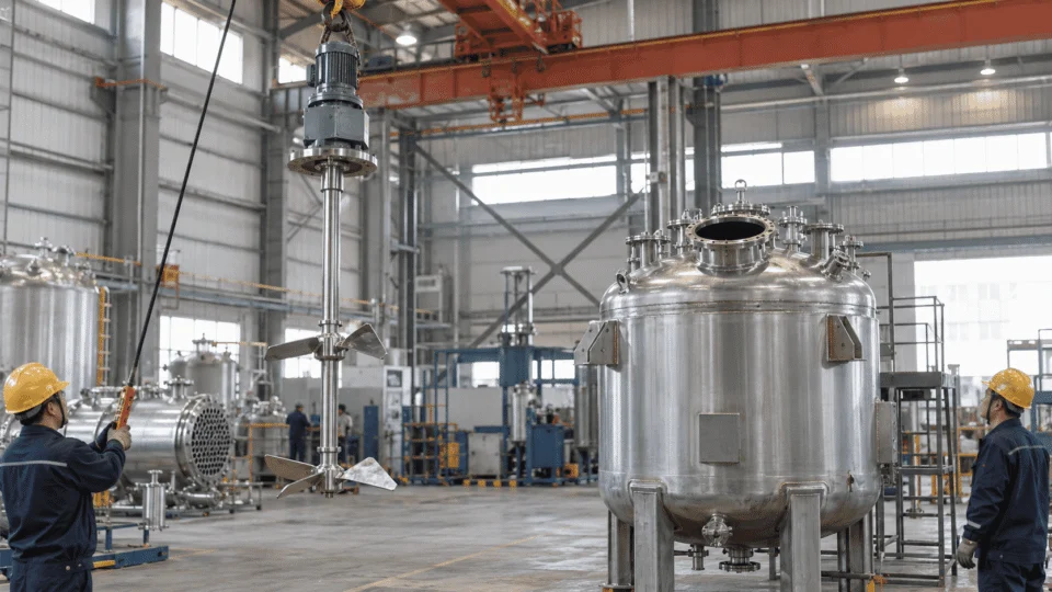
Agitated reactor agitator installation in factory
Engineering check before fabrication

Confirm the agitator envelope, shaft loading, nozzle orientation, minimum working level and internal clearances before the vessel is released to production.

Choosing the agitator by RPM alone
Why it fails

RPM does not show torque, flow pattern, tip speed or power demand.

Better check

Review duty, viscosity, impeller diameter, power and torque together.

Sizing the motor before defining the process duty
Why it fails

Motor power can be meaningless if the required mixing objective is still unclear.

Better check

Define blending, suspension, dispersion, heat-transfer or shear duty first.

Using one viscosity value for the whole batch
Why it fails

Polymerization, concentration or cooling can change viscosity dramatically.

Better check

Provide initial, maximum and final viscosity whenever the batch changes.

Ignoring the minimum working level
Why it fails

An upper impeller may become partially exposed or lose useful circulation.

Better check

Verify impeller immersion at both minimum and maximum batch levels.

Adding coils or nozzles after the agitator is finalized
Why it fails

Late internals can block circulation or enter the mechanical shaft envelope.

Better check

Coordinate internals, nozzles, P&ID and agitator layout before fabrication.

Selecting the seal only from vessel pressure
Why it fails

Temperature, fluid compatibility, shaft movement and leakage requirement also matter.

Better check

Define the complete seal duty before choosing the seal arrangement.

Scaling a pilot reactor by keeping the same RPM
Why it fails

Tip speed, power per volume, circulation and shaft loading change with scale.

Better check

Define which scale-up criterion matters for the process before resizing.

A quiet agitator is not automatically a safe agitator.

Shaft deflection, critical speed, coupling alignment and dynamic loads should be checked before vibration becomes a field problem.

Shaft deflection Critical speed Bearing load Coupling alignment Seal movement Support stiffness
MATERIALS, FABRICATION & INSPECTION

The Reactor Design Is Only as Good as the Fabrication Behind It

Material control, welding quality, dimensional accuracy, pressure testing and final documentation should be planned as part of the reactor package—not added after fabrication is complete.
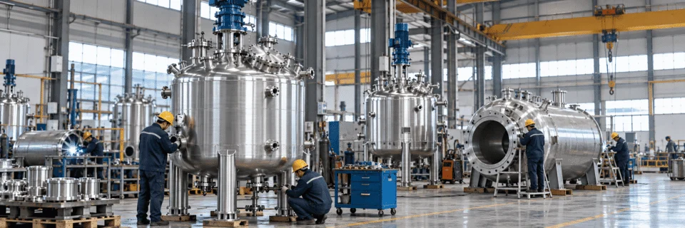
Stainless steel reactor fabrication and inspection in factory
MATERIAL

Material Verification

Base material, wetted parts and special alloys should match the process medium, corrosion risk and cleaning requirement.

Typical Check Material grade confirmation
Typical Check Heat / batch traceability
Typical Check Wetted-part consistency
Material Selection →
FABRICATION

Welding & Assembly

Shell, heads, nozzles, jacket, supports and agitator mounting features should be assembled with dimensional control and process-specific weld requirements.

Typical Check Weld preparation & fit-up
Typical Check Nozzle orientation
Typical Check Agitator mounting alignment
Fabrication & Welding →
INSPECTION

Inspection & Testing

The final inspection plan depends on the design code, service condition, customer specification and any required nondestructive examination.

Typical Check Dimensional inspection
Typical Check NDT as specified
Typical Check Pressure / leak testing
Inspection & Testing →
DOCUMENTS

Final Project Dossier

Documentation should match the agreed project scope so the reactor can be installed, inspected and maintained with a clear record of the supplied configuration.

Possible Deliverable GA / fabrication drawings
Possible Deliverable Material & inspection records
Possible Deliverable Test documentation
Codes & Standards →
Code and documentation scope should be confirmed before quotation.

Different destination markets can require different design, conformity-assessment and documentation paths.

EU Pressure Equipment Directive 2014/68/EU ↗
APPLICATIONS & RELATED REACTORS

Agitated Reactors for Different Process Conditions

The vessel geometry, agitator, seal and thermal system should change with the process—not just the industry name. Typical applications range from low-viscosity blending to solids suspension, gas dispersion and high-viscosity reaction service.

Chemical industry reactor equipment
CHEMICAL PROCESSING

Reaction, neutralization, blending and batch processing

Chemical service can require corrosion-resistant materials, pressure capability, controlled heat transfer and agitation selected around viscosity and reaction behavior.

Chemical Industry →
Pharmaceutical stainless steel process equipment
PHARMACEUTICAL

Controlled batch processing

Material compatibility, cleanability, sealing and process control can become primary design inputs.

Pharmaceutical Industry →
Food and beverage process equipment
FOOD & BEVERAGE

Blending, heating and formulation

Hygienic details, product shear sensitivity and temperature response can influence the reactor configuration.

Food & Beverage →
Petrochemical process equipment
PETROCHEMICAL

Pressure, temperature and containment driven service

Process pressure, temperature, hazardous-area requirements and seal duty often become major design considerations.

Petrochemical Industry →
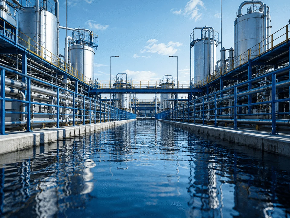
Water treatment process equipment
WATER TREATMENT

Chemical preparation and treatment processes

Agitation may be used for reagent preparation, solids management, pH adjustment and other treatment duties.

Water Treatment →
Custom process equipment and new energy processing system
CUSTOM PROCESS DUTY

Engineered around the actual batch

When the process does not fit a standard application category, start from fluid properties, mixing duty and thermal requirements.

Discuss Your Process →
CUSTOM AGITATED REACTOR

Send the Process Duty Before You Send the Motor Size

Share the working volume, viscosity range, solids or gas conditions, operating pressure, operating temperature and required mixing objective. We can review the reactor, agitator, seal and thermal system together.

Working Volume Viscosity Range Pressure / Temperature Mixing Objective Heating / Cooling Duty
Scroll to Top
DRAWING & FILE REVIEW

Send Your Drawings

Upload your drawings, datasheets or existing specifications. Our engineering team will review the files and respond with technical feedback.

Engineering Review

Drawings, specifications and process requirements

Confidential File Handling

Project files are used only for technical review and quotation

Faster Technical Feedback

Clearer inputs help us respond more accurately and efficiently

DRAWING & FILE REVIEW

Send Your Drawings

Upload your drawings, datasheets or specifications. Our engineering team will review your files and provide technical feedback.

Contact Form Demo (#3)
Project Protected NDA available
12h Response
ASME / PED
AFTER SUBMISSION
01 Review
→
02 Confirm
→
03 Quote
TECHNICAL QUOTATION

Get a
Technical Quote

Tell us what you need. Our engineering team will review your requirements and respond within 12 hours.

Engineered for Your Application

From concept to certified manufacturing

Global Compliance

ASME, PED and other international standards

Expert Support

Direct access to our engineering team

TECHNICAL QUOTATION

Get a Technical Quote

Tell us what you need. Our engineering team will review your requirements and respond within 12 hours.

Contact Form Demo
Project Protected NDA available
12h Response
ASME / PED
AFTER SUBMISSION
01 Review
→
02 Confirm
→
03 Quote