
ChannelVessel Intelligent Equipment Co., Ltd. Contact Us
CUSTOM VERTICAL PRESSURE VESSEL MANUFACTURER

Vertical Pressure Vessels

Custom-engineered vertical pressure vessels built around your process conditions and project requirements. Configure the vessel for the required pressure, temperature, material, capacity, supports, nozzles, internals, and inspection scope.
Custom Engineered
Material Options
Custom Configuration
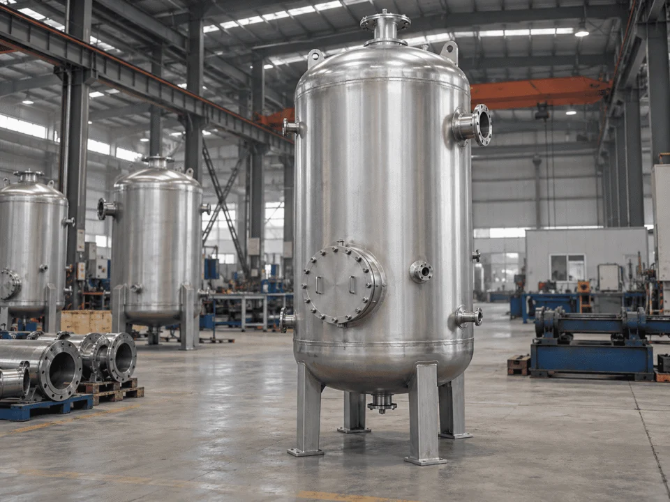
Custom vertical pressure vessels manufactured in an industrial workshop

Engineered for project-specific pressure, temperature, materials, supports, nozzles, internals, and inspection requirements.

ENGINEERED AROUND THE SERVICE

Custom Vertical Pressure Vessels for Process & Industrial Service

A vertical pressure vessel should be selected around the actual process duty, not simply by choosing a diameter, height, and pressure rating from a standard list.

The starting point is the service condition. Pressure, temperature, media, volume, corrosion risk, internals, nozzle arrangement, support method, inspection scope, and site constraints all affect the final vessel configuration.

ChannelVessel manufactures vertical pressure vessels for applications where a compact footprint, vertical process arrangement, gravity-assisted drainage, liquid hold-up, gas separation, surge capacity, or internal process components make a vertical configuration more practical.

The vessel can be engineered as a simple pressure shell or as a more application-specific unit with process nozzles, manways, internal piping, demisters, distributors, support rings, heating or cooling provisions, instrumentation connections, insulation attachments, and project-specific inspection requirements.

Process duty
Define what the vessel must actually do: store, separate, buffer, flash, receive, hold, collect, or support another process step. The operating function determines many of the dimensions and internal details that follow.
Operating conditions
Design pressure, operating pressure, design temperature, vacuum conditions, cyclic loading, fluid properties, corrosion allowance, and expected service life should be reviewed together rather than treated as isolated data points.
Physical configuration
Vessel diameter, straight-side height, head type, nozzle orientation, manway access, internals, supports, lifting points, and overall height must work with the process layout and the available installation space.
Fabrication & inspection
Material grade, welding requirements, NDT scope, pressure testing, surface treatment, documentation, and any applicable design code need to be defined early enough to avoid costly changes after fabrication begins.
A well-defined specification gives you:
More accurate vessel sizing Cleaner nozzle coordination Fewer fabrication changes More reliable quotation scope
DESIGN CAPABILITIES

Vertical Pressure Vessel Design Capabilities

A workable vessel design has to connect process requirements with mechanical limits, fabrication realities, inspection access, and site constraints. The design envelope is developed from the service conditions first, then translated into a vessel geometry that can be built, tested, transported, and installed reliably.

What defines the design basis

Start with the operating case, not with a vessel diameter.

Capacity alone is not enough to define a pressure vessel. Pressure, temperature, fluid behavior, liquid level, corrosion risk, vacuum exposure, cyclic service, and upset conditions can materially change the required wall thickness, geometry, materials, and inspection scope.

Pressure & temperature Operating, design, upset, vacuum, and hydrotest conditions are reviewed together so the mechanical basis reflects the real service envelope.
Media & phase behavior Fluid composition, density, vapor space, solids, corrosiveness, and gas-liquid behavior affect sizing assumptions and internal arrangement.
Required volume Working volume, surge volume, residence time, liquid level, freeboard, and process hold-up determine the usable geometry rather than nominal capacity alone.
Service severity Cyclic duty, fatigue-sensitive operation, low-temperature service, corrosive duty, and abnormal load cases are considered before dimensions are finalized.
Turning requirements into geometry

Build a vessel envelope that works mechanically and physically.

Once the service basis is defined, the vessel can be developed around diameter, straight-side height, overall height, working volume, wall thickness, head allowance, access clearances, and practical fabrication limits.

Diameter & height The aspect ratio is coordinated with process duty, available footprint, internal requirements, fabrication practicality, and transport or installation limits.
Mechanical thickness Required shell and head thicknesses depend on pressure, temperature, material properties, corrosion allowance, joint efficiency, and applicable design rules.
Load cases Empty, operating, hydrotest, wind, seismic, lifting, transport, insulation, platform, and connected-equipment loads can all influence the final arrangement.
Fabrication reality Plate width, forming limits, weld access, inspection access, shop handling, lifting, and shipment size are checked before the design is released for fabrication.
Coordinating the vessel with the project

The vessel has to fit the plant, not just pass a calculation.

Connections, access, instrumentation, internals, supports, lifting points, adjacent piping, insulation, platforms, and maintenance clearance all need to be coordinated before fabrication starts.

Nozzle coordination Connection size, rating, orientation, projection, elevation, reinforcement, and access are aligned with the piping and instrument layout.
Access & maintenance Manways, inspection openings, removable internals, drain points, lifting access, and maintenance clearances are positioned around actual service needs.
Site integration Foundation limits, platform elevations, surrounding steelwork, adjacent equipment, lifting routes, and installation sequence can affect the vessel configuration.
Drawing control General arrangement, nozzle orientation, support details, internals, and project interfaces should be confirmed before material cutting and fabrication progress too far.
Design capability means controlling the interfaces. A vessel can satisfy a pressure calculation and still create problems if nozzle locations, access, lifting, transport, maintenance, or installation constraints are resolved too late.
VESSEL CONFIGURATION DETAILS

Heads, Nozzles, Internals & Thermal Options

These details are not secondary accessories. They determine how the vessel connects to the process, how operators inspect and maintain it, how fluids move inside it, and whether heating or cooling can be integrated without creating avoidable fabrication or service problems.
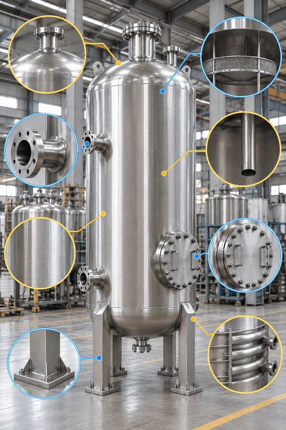
Vertical pressure vessel configuration showing heads, nozzles, internals and thermal options
Configuration should be resolved before fabrication. Nozzle orientation, internal supports, access openings, jackets, coils, and attachment details are much easier to coordinate before plate cutting and welding begin.

Head geometry affects internal volume, overall height, stress distribution, fabrication complexity, drainage, and the space available for nozzles or internals near the vessel ends.

Common options Ellipsoidal, torispherical, hemispherical, conical, and flat closures may be considered depending on service, pressure level, geometry, and fabrication requirements.
Selection factors Design pressure, vessel diameter, available height, drainage needs, internal arrangement, cost, and code requirements all influence the preferred head form.

Nozzles have to work mechanically and spatially. Their size, rating, orientation, elevation, projection, reinforcement, and local loads must fit the process piping and instrumentation layout.

Connection planning Process inlet and outlet, vent, drain, relief, instrument, sampling, cleaning, level, and utility connections should be coordinated as one nozzle schedule.
Access planning Manways and inspection openings need enough clearance for personnel access, internal removal, inspection tools, bolting, and future maintenance activities.

Internal components can change the vessel from a simple pressure shell into a process unit. Their loads, clearances, supports, removability, and welding details should therefore be included in the engineering scope.

Typical internals Demisters, inlet devices, distributors, baffles, vortex breakers, calming plates, support rings, trays, screens, dip pipes, and internal piping may be incorporated where the process requires them.
Maintenance access Where internals need periodic cleaning, replacement, or inspection, the arrangement should allow realistic removal paths rather than relying on theoretical assembly space.

When process temperature has to be controlled, thermal features should be designed as part of the vessel rather than added after the mechanical layout has been fixed.

Thermal options External jackets, half-pipe coils, internal coils, thermal-fluid connections, insulation clips, and tracing provisions can be selected around the required duty and maintenance strategy.
Engineering impact Thermal expansion, jacket pressure, local stresses, weld accessibility, drainability, nozzle routing, and inspection access can all affect the final mechanical arrangement.
SUPPORT & INSTALLATION ENGINEERING

Support & Installation Engineering

The vessel support system has to carry more than operating weight. Empty, operating, hydrotest, wind, seismic, piping, platform, insulation, lifting, transport, and maintenance loads can all influence the final support arrangement.

Support selection should therefore be coordinated with the vessel geometry, site layout, foundation design, access requirements, and installation sequence before fabrication details are finalized.

Skirt Support

Common for taller or heavier vertical vessels where continuous support around the lower shell provides a direct load path into the foundation.

Typical use
Tall vessels, larger diameters, higher wind or seismic demand
Key coordination
Anchor bolts, skirt access, base ring, insulation, drain clearance

Leg Support

Suitable for many smaller and medium-size vertical vessels where open access below the shell and a simpler support arrangement are preferred.

Typical use
Compact vessels, process receivers, vessels requiring bottom access
Key coordination
Leg spacing, gussets, base plates, nozzle clearance, local shell loads

Support Lugs

Useful where the vessel is supported from surrounding structure rather than directly from a conventional base or foundation.

Typical use
Elevated installations, structural frames, compact process layouts
Key coordination
Lug elevation, shell reinforcement, structural interface, access
INSTALLATION CONDITIONS

The support works only when the vessel and the site are engineered together.

Final support details should reflect the actual installation environment rather than being treated as a standard fabrication attachment.

Foundation & Anchor Loads

Operating weight, hydrotest weight, overturning moment, shear, anchor tension, base reactions, and grout or base-plate requirements need to be available for civil and structural coordination.

Wind & Seismic Loads

Vessel height, diameter, center of gravity, attached platforms, insulation, connected piping, and local site criteria can materially change support and anchoring requirements.

Lifting & Transport

Lifting lugs, trunnions, temporary bracing, transport orientation, center of gravity, shipping height, route restrictions, and site erection sequence should be reviewed before shipment.

Access & Maintenance

Support geometry must leave realistic clearance for bottom nozzles, drains, instruments, insulation, bolting, manway access, internal removal, and routine inspection activities.

Support details should be frozen only after vessel loads, site criteria, foundation interfaces, lifting requirements, and maintenance clearances are coordinated with the project layout.

ENGINEERING AROUND THE SERVICE

How We Engineer the Vessel Around Your Service

A vertical pressure vessel should not be engineered from nominal capacity alone. The design develops by translating process data, operating conditions, mechanical requirements, and project interfaces into a vessel configuration that can be fabricated and installed without unnecessary compromises.

Service Input
Engineering Decision
What It Changes
Process function

Storage, separation, surge, receiver, flash, collection, or another defined process duty.

Define the usable process volume and internal operating space.

Working level, vapor space, freeboard, residence time, hold-up, and internal equipment are considered before setting final dimensions.

Diameter Straight-side height Head volume Internal layout
Pressure & temperature

Operating, design, upset, vacuum, and test conditions across the expected service range.

Establish the mechanical design envelope.

Material strength, required wall thickness, corrosion allowance, joint efficiency, head geometry, and code calculations are coordinated around the governing condition.

Shell thickness Head thickness Material grade Reinforcement
Media & corrosion risk

Fluid composition, contaminants, solids, cleaning media, corrosion tendency, and product-contact requirements.

Select materials and surface requirements around the actual medium.

Base material, corrosion allowance, lining or cladding needs, weld consumables, finish, passivation, and cleaning requirements are reviewed together.

Material selection Corrosion allowance Surface finish Welding scope
Connections & internals

Nozzles, manways, instruments, dip pipes, demisters, distributors, baffles, and process hardware.

Coordinate the vessel as part of the process system.

Nozzle orientation, elevations, reinforcement, internal supports, access paths, removable components, and maintenance clearances are resolved before fabrication.

Nozzle schedule Manway access Internal supports Maintenance space
Site & project constraints

Foundation, wind, seismic, transport, lifting, surrounding steelwork, platforms, insulation, and erection limits.

Make the vessel buildable, movable, and installable.

Support arrangement, anchor loads, lifting points, overall envelope, shipping orientation, site clearances, and project documentation are checked before release.

Support type Anchor loads Lifting details Overall envelope
The engineering result should be one coordinated vessel specification.

Process, mechanical, fabrication, inspection, transport, and installation requirements should converge into the same drawing and documentation package before fabrication progresses too far.

MATERIALS & CORROSION SELECTION

Materials & Corrosion Selection

Material selection should follow the actual service environment, not a default preference for carbon steel or stainless steel. Fluid chemistry, temperature, chlorides, contamination tolerance, cleaning requirements, corrosion rate, fabrication method, and expected service life all affect the final choice.

SELECTION LOGIC

Choose the corrosion strategy before choosing the final material grade.

What is inside the vessel?

Fluid composition, concentration, impurities, solids, moisture, dissolved gases, and possible contaminants can change the corrosion mechanism.

What temperature will the material actually see?

Operating, cleaning, upset, steam, and thermal-cycle temperatures can affect corrosion rate, material strength, and the suitability of coatings or linings.

How much corrosion can the process tolerate?

Some duties can use a calculated corrosion allowance, while contamination-sensitive or high-purity services may require corrosion-resistant alloys or protected surfaces.

How will the vessel be cleaned and maintained?

Cleaning chemicals, washdown, passivation, product-change requirements, access, and inspection intervals should be considered as part of the material strategy.

What is the lifecycle cost?

Lower initial material cost can be offset by higher corrosion allowance, maintenance, lining replacement, downtime, contamination risk, or shorter service life.

Material
Typical Direction
Engineering Attention
Carbon Steel Cost-efficient base option

Common where the process medium is compatible and corrosion can be controlled through allowance, coating, lining, or operating conditions.

Review corrosion rate, contamination tolerance, internal coating requirements, low-temperature properties, and external corrosion protection.

304 / 304L General stainless service

Suitable for many clean, mildly corrosive, food, water, utility, and process applications where higher corrosion resistance than carbon steel is needed.

Review chlorides, cleaning chemistry, temperature, crevice conditions, and whether product-contact finish or passivation is required.

316 / 316L Higher corrosion resistance

Often selected where molybdenum-bearing stainless steel provides better resistance in more demanding process, chloride, or cleaning environments.

Chloride concentration, temperature, stagnant zones, crevices, weld condition, surface finish, and stress-corrosion risk still need to be checked.

Duplex Stainless Strength + corrosion resistance

Considered where higher mechanical strength and improved resistance to certain chloride-containing environments can reduce thickness or improve service performance.

Welding procedure, heat input, phase balance, forming, inspection, and fabrication control become more important than with conventional austenitic stainless steels.

Nickel Alloy Severe corrosion duty

Used where conventional stainless steels are not suitable for the chemical environment, temperature, or corrosion mechanism.

Alloy selection should be tied closely to the actual chemistry, welding requirements, availability, fabrication route, inspection scope, and project cost.

Corrosion strategy can also change the vessel construction
Corrosion Allowance

Additional base-metal thickness is provided where predictable material loss is acceptable over the intended service life.

Lining or Cladding

A corrosion-resistant barrier can protect the pressure-retaining base material when full solid-alloy construction is unnecessary or uneconomical.

Solid Corrosion-Resistant Alloy

The pressure-retaining shell itself is fabricated from the selected corrosion-resistant material where service severity or contamination control requires it.

CODES, FABRICATION & QUALITY CONTROL

Codes, Fabrication & Quality Control

Pressure-vessel quality depends on more than the final pressure test. The applicable design basis, material traceability, welding controls, inspection scope, dimensional checks, testing, and release documentation should be defined before fabrication progresses.

FABRICATION QUALITY GATES

Each stage should close the critical issues that would become difficult or expensive to correct later.

Design & Code Basis Before material release

Confirm the governing design code, project specification, design pressure and temperature, corrosion allowance, load cases, joint assumptions, nozzle schedule, support concept, and required inspection scope before fabrication drawings are released.

Approved design basis Released fabrication drawings
Material Control Before cutting and forming

Verify material grade, thickness, heat or lot identification, certificates, traceability markings, substitution controls, and any project-specific impact, corrosion, or supplementary requirements before material enters production.

Material traceability Controlled release to production
Welding & NDT During fabrication

Control joint preparation, fit-up, welding procedures, welder qualification, consumables, heat input, interpass condition, repair records, and the required visual, surface, ultrasonic, radiographic, or other examination scope.

Controlled weld quality Recorded examination results
Testing & Final Release Before shipment

Complete pressure testing, dimensional inspection, nozzle orientation checks, support and attachment verification, surface treatment, cleaning, final visual inspection, nameplate or marking requirements, and release documentation before shipment.

Verified final condition Release package complete
DOCUMENTATION & MANUFACTURING DOSSIER

Documentation & Manufacturing Dossier

A pressure vessel is not fully delivered when fabrication is complete. The documentation package should provide traceable evidence of the agreed design basis, materials, welding, examination, testing, inspection, and final release status.

THE DOSSIER HAS A JOB

It should let the buyer verify what was designed, built, inspected, and released.

The exact content depends on the applicable code, project specification, inspection plan, and contractual scope. The required records should therefore be agreed before fabrication begins rather than assembled only at the end.

Missing or late-defined documentation requirements can create rework even when the physical vessel itself is already complete.

Design Records

Records that define the approved engineering basis and the vessel configuration released for fabrication.

Approved GA drawing Design calculations Nozzle schedule Support details Applicable design code
Material Records

Evidence that pressure-retaining and specified project materials can be traced back to the agreed grade, thickness, and certification scope.

Material certificates Heat or lot traceability Material identification Substitution records Supplementary test records
Welding & NDT Records

Records supporting the welding process, welder qualification, repair control, and the examination methods required by the project.

WPS / PQR references Welder qualifications Weld maps NDT reports Repair records
Testing & Inspection Records

Evidence that the vessel was inspected and tested against the agreed fabrication and acceptance requirements before release.

Pressure-test record Dimensional inspection Visual inspection Surface treatment record Inspection release notes
Final Release Records

Documents that confirm the final configuration, release status, marking, and handover condition of the completed vessel.

As-built drawings Final inspection release Nameplate or marking data Packing records Manufacturing data package
What the buyer should be able to verify from the final package
The vessel matches the approved design basis
Specified materials are traceable
Required welding and NDT records are complete
Testing and inspection results are recorded
The delivered configuration matches the final drawings
The agreed release documentation is included
APPLICATIONS BY INDUSTRY

Vertical Pressure Vessels Across Process Industries

Vertical pressure vessels are used wherever process duty, plant footprint, liquid hold-up, separation, storage under pressure, surge capacity, or internal process hardware makes a vertical arrangement practical. The final configuration should still be engineered around the specific medium, operating conditions, code requirements, and site constraints of each industry.

Chemical industry process equipment

Chemical & Petrochemical

Corrosive and process-intensive service

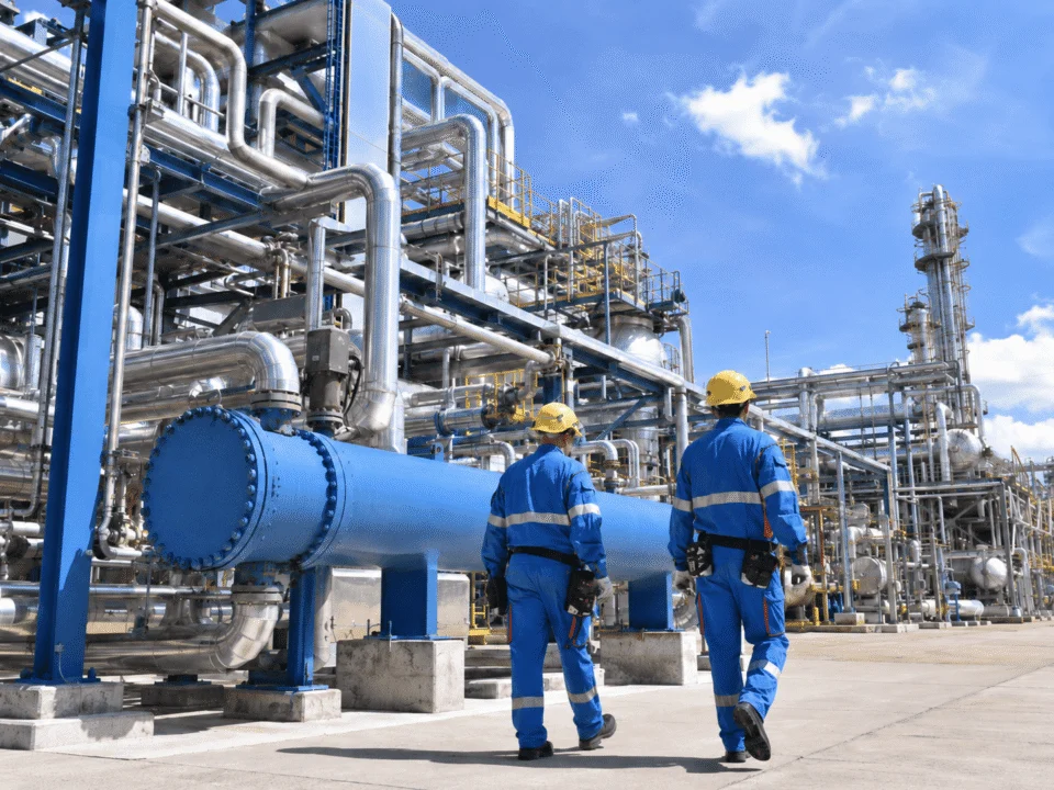
Used for process receivers, separators, surge vessels, flash vessels, intermediate hold-up, feed service, and other duties where pressure, temperature, corrosion, internals, and nozzle layout must be coordinated together.
Process receivers Flash service Surge duty
Oil and gas process equipment

Oil & Gas

Separation, collection and pressure service

Vertical vessels can be applied to gas-liquid separation, knockout, collection, buffer, scrubber, and receiver duties where compact footprint and internal separation hardware are important.

Knockout vessels Scrubber service Pressure receivers
Food and beverage process equipment

Food & Beverage

Cleanability and product-contact control

Pressure-rated vertical vessels may be configured for hygienic product handling, buffer service, utility duty, process hold-up, and pressure-supported operations where material finish, drainability, cleaning, and contamination control matter.

Buffer vessels Clean process service Utility duty
Pharmaceutical stainless steel process equipment

Pharmaceutical

Controlled materials and documentation

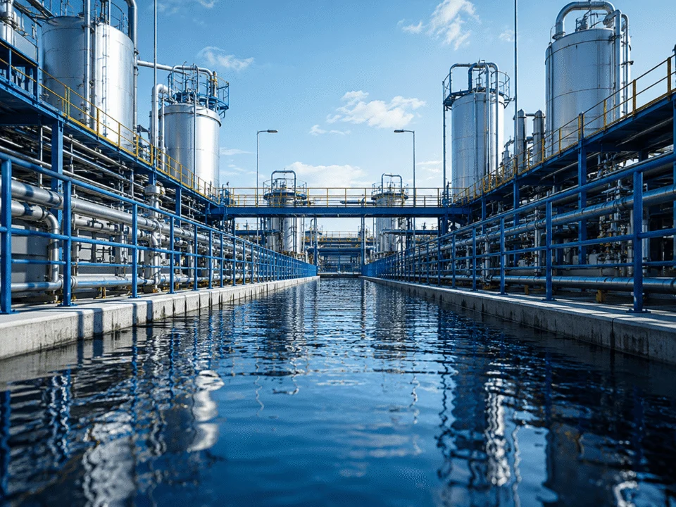
Applications may require stainless or higher-alloy construction, controlled surface finish, cleaning access, traceable documentation, carefully coordinated instrumentation, and tighter control of fabrication details.
High-purity service Process hold-up Utility vessels
Water treatment pressure vessel equipment

Water Treatment

Utility, filtration and treatment service

Vertical pressure vessels can support filtration, treatment, air or gas service, chemical dosing systems, process water, and other utility duties where corrosion resistance and long-term maintainability are important.

Filter vessels Utility receivers Treatment systems
New energy process equipment manufacturing

New Energy

Corrosion, sealing and clean process control

Vertical pressure vessels can support battery materials, solvent handling, reaction, storage, separation, and thermal-process duties where material compatibility, sealing, cleanliness, and project-specific process conditions affect the design.

Process vessels Solvent service Thermal processes
The industry changes the engineering priorities.

The same vertical vessel geometry can require very different materials, internal details, surface treatment, inspection scope, documentation, and maintenance access depending on the process and operating environment.

VERTICAL VS HORIZONTAL

Vertical vs Horizontal Pressure Vessels

Vessel orientation should follow the process and site constraints rather than a fixed preference. Vertical and horizontal vessels can perform similar pressure-containing duties, but their footprint, liquid behavior, internals, supports, maintenance access, and transport envelope can be very different.

Design Consideration
Vertical Pressure Vessel Compact footprint and vertical process arrangement
Horizontal Pressure Vessel Lower profile and extended liquid interface
Footprint & Plot Space

Uses less ground area and is often easier to fit into compact process layouts where vertical height is available.

Requires more horizontal plot area but keeps the overall equipment height lower.

Liquid Hold-up & Drainage

Can support gravity-assisted drainage, bottom collection, narrow liquid-level control zones, and tall liquid columns.

Provides a longer liquid interface and can be useful where liquid surge volume or level control benefits from a broader horizontal geometry.

Separation & Internals

Often well suited to vertical gas-liquid flow, demisters, distributors, trays, dip pipes, internal piping, and stacked process zones.

Can provide longer disengagement distance and a wider liquid surface, which may suit specific separator or receiver duties.

Access & Maintenance

Manway elevations, ladders, platforms, internal access, and removal paths need careful coordination because components may be distributed vertically.

Side access can be easier at lower elevations, but long shells may require more lateral clearance for inspection and maintenance.

Supports & Foundation

Skirts, legs, or support lugs may be used. Wind, seismic, overturning moment, anchor loads, and foundation reactions can become significant as height increases.

Saddle supports are common. Foundation loads are distributed along the vessel length, while local shell stresses around saddles require attention.

Transport & Overall Envelope

Tall vessels may need shipment in a horizontal orientation and field erection, with lifting strategy and site crane access considered early.

Lower installed height can simplify erection, but vessel length may create road, turning-radius, shipping, and site-access constraints.

SELECTION PRINCIPLE

Orientation should follow the duty, not the drawing habit.

A vertical configuration is often attractive when footprint is limited, gravity drainage matters, internals are arranged vertically, or the process benefits from a tall vessel geometry.

A horizontal configuration can be appropriate when lower installed height, extended liquid surface, longer disengagement length, or horizontal access better matches the process and site.

COST & LEAD TIME DRIVERS

What Changes Cost & Lead Time?

Pressure-vessel cost and manufacturing lead time are driven by the total engineering and fabrication scope, not by vessel volume alone. Material grade, wall thickness, nozzle complexity, inspection requirements, surface treatment, documentation, and material availability can change both quotation value and production sequence.

PROCUREMENT REALITY

Two vessels with similar dimensions can have very different manufacturing scope.

Material and thickness influence raw-material cost, forming, welding, handling, and procurement time.

Inspection, documentation, and approval requirements can add hold points before fabrication can move forward.

Complex internals, attachments, and surface requirements increase fabrication and finishing operations.

Material & Alloy

Carbon steel, stainless steel, duplex, nickel alloys, clad construction, and lined vessels have different material prices, sourcing routes, forming requirements, welding procedures, and fabrication controls.

Raw-material availability Welding procedure Fabrication control
Vessel Size & Wall Thickness

Larger diameter, greater straight-side height, thicker plate, heavier heads, and higher total vessel weight affect material quantity, forming, welding time, shop handling, lifting, testing, and transport planning.

Plate quantity Forming effort Handling & transport
Nozzles, Internals & Attachments

Large nozzles, reinforced openings, multiple instrument connections, manways, internal piping, demisters, distributors, support rings, platforms, ladders, clips, and other attachments add fabrication steps and coordination work.

Weld count Fit-up complexity Engineering coordination
Code, NDT & Inspection Scope

Design-code requirements, additional NDT, third-party inspection, witness points, supplementary material testing, heat treatment, special acceptance criteria, and project-specific inspection plans can affect both cost and fabrication sequence.

Inspection hold points Testing scope Approval sequence
Surface Treatment & Cleanliness

Blasting, painting, polishing, pickling, passivation, controlled stainless finish, cleaning, contamination prevention, and special product-contact requirements add finishing operations and may require dedicated handling.

Finishing operations Cleaning control Final inspection
Availability & Fabrication Complexity

Non-standard plate thicknesses, special forgings, uncommon flanges, large formed heads, alloy fittings, imported components, unusual dimensions, or restricted transport envelopes can add procurement and production constraints.

Supplier lead time Special procurement Production scheduling
FOR A MORE RELIABLE QUOTATION

Freeze the major scope drivers before comparing prices.

Quotations are easier to compare when bidders are working from the same design pressure and temperature, material grade, corrosion allowance, vessel geometry, nozzle schedule, internals, support type, NDT scope, surface treatment, documentation, and delivery requirements.

COMMON PURCHASING MISTAKES

Common Vertical Pressure Vessel Purchasing Mistakes

Many pressure-vessel problems start before fabrication begins. An incomplete specification can create scope gaps, late drawing revisions, material changes, nozzle conflicts, inspection delays, or quotations that are difficult to compare on an equal basis.

Common Mistake
What It Can Change
Better Purchasing Approach
Selecting by nominal volume alone

Buying from capacity before defining the actual process duty.

Working level, vapor space, residence time, freeboard, internals, and process hold-up may make the usable volume very different from the nominal vessel capacity.

Define the usable process volume first.

State the required working volume, liquid level, vapor space, process function, and any internal equipment before finalizing diameter and height.

Using unclear pressure or temperature data

Providing only normal operating conditions.

Wall thickness, material strength, vacuum design, head thickness, relief conditions, testing, and code calculations may all depend on the governing design case rather than the normal operating point.

Separate operating and design conditions.

Define operating pressure, design pressure, operating temperature, design temperature, vacuum, upset cases, and any cyclic or abnormal conditions.

Specifying only “stainless steel”

Leaving the actual grade and corrosion basis undefined.

304L, 316L, duplex, nickel alloy, clad construction, and carbon steel with lining can have very different corrosion performance, fabrication controls, availability, and cost.

Tie material selection to the medium.

Provide fluid chemistry, concentration, temperature, chlorides, cleaning media, corrosion allowance, finish requirements, and contamination limits where relevant.

Freezing nozzles too late

Starting fabrication before connections are coordinated.

Late nozzle changes can affect reinforcement, local stresses, internals, weld access, manway clearance, piping layout, instrument elevations, and sometimes shell-course arrangement.

Approve the nozzle schedule before material cutting.

Confirm size, rating, service, orientation, elevation, projection, flange standard, instrument connections, manways, vents, drains, and relief connections early.

Ignoring installation and transport limits

Treating the vessel as a shop-only fabrication item.

Overall height, support type, anchor loads, lifting points, shipping orientation, route restrictions, crane access, surrounding steelwork, and maintenance clearance may force design changes later.

Design with the site and logistics in mind.

Share foundation limits, transport envelope, erection sequence, lifting restrictions, platform elevations, surrounding equipment, and required maintenance access.

Leaving inspection and documents until the end

Treating NDT and dossier requirements as final paperwork.

Additional NDT, witness points, material certification, welding records, third-party inspection, supplementary testing, and final documentation can affect the fabrication sequence long before shipment.

Define the inspection plan with the purchase scope.

Agree the design code, NDT extent, hold points, testing, certificates, inspection release, as-built drawings, and final manufacturing dossier before fabrication starts.

PROCUREMENT CHECK

Compare quotations only after the technical scope is aligned.

A lower price can simply reflect a smaller inspection scope, different material assumption, fewer nozzles, less documentation, excluded internals, or a different support and delivery scope. Technical alignment should come before price comparison.

WHAT TO SEND FOR A QUOTE

What to Send for an Accurate Quote

A useful quotation needs enough technical information to define the vessel scope. The more clearly pressure, temperature, material, size, nozzles, internals, supports, inspection, and documentation are specified, the fewer assumptions have to be made during pricing.

Start with the information that defines the vessel.

Process duty & required volume

State what the vessel must do and the required working, nominal, surge, or hold-up volume.

Operating & design conditions

Provide operating pressure, design pressure, operating temperature, design temperature, vacuum, and relevant upset conditions.

Material requirement

Specify the intended material grade, corrosion allowance, lining or cladding requirement, and any product-contact or finish requirement.

Approximate vessel geometry

Provide diameter, straight-side height, overall height, available footprint, or any dimensional limit already defined by the project.

Nozzles, manways & connections

Include service, size, rating, orientation, elevation, projection, instrument connections, drains, vents, and relief connections where available.

These details improve scope accuracy and reduce later revisions.

Internals & process hardware

Demisters, distributors, dip pipes, baffles, trays, support rings, internal coils, or other internal components.

Support & site conditions

Skirt, legs, support lugs, wind or seismic criteria, anchor requirements, foundation limits, platforms, and installation constraints.

Inspection & testing scope

Design code, NDT extent, third-party inspection, witness points, pressure-test requirements, supplementary testing, and acceptance criteria.

Surface treatment & finish

Painting, blasting, pickling, passivation, polishing, cleaning, insulation attachments, or product-contact finish requirements.

Documentation requirements

Material certificates, calculations, weld records, NDT reports, inspection records, as-built drawings, and manufacturing dossier expectations.

Drawings or existing specification

A process datasheet, GA drawing, nozzle orientation sketch, P&ID extract, previous vessel drawing, or project specification can greatly reduce quotation assumptions.

BEFORE YOU REQUEST A PRICE

Make sure every bidder is pricing the same technical scope.

Same design conditions Same material grade Same nozzle scope Same NDT requirement Same documentation scope Same delivery boundary
READY FOR A TECHNICAL QUOTATION?

Send the vessel data you already have. Missing details can be clarified during the engineering review.

You can start with a datasheet, drawing, equipment list, process information, or a written requirement.

VERTICAL PRESSURE VESSEL FAQ

Vertical Pressure Vessel FAQ

These are some of the most common technical and purchasing questions raised when specifying a custom vertical pressure vessel. Final requirements should still be confirmed against the actual process conditions, project specification, and applicable design code.

BEFORE YOU FINALIZE THE SPECIFICATION

Use the FAQ to check the main engineering decisions before requesting a final quotation.

Confirm the process duty and usable volume.

Separate operating conditions from design conditions.

Define material, corrosion, nozzles, internals, and supports.

Agree inspection, testing, and documentation before fabrication.

Vessel sizing should start with the process duty, required working or hold-up volume, liquid level, vapor space, operating pressure and temperature, design conditions, fluid properties, internals, nozzle requirements, and available installation space. Nominal capacity alone is usually not enough to define the final diameter and height.

The applicable design code depends on the project, installation location, purchaser specification, regulatory requirements, and contractual scope. The code basis should be identified before calculations, material release, fabrication drawings, inspection planning, and documentation requirements are finalized.

Common options include carbon steel, 304 or 304L stainless steel, 316 or 316L stainless steel, duplex stainless steel, nickel alloys, and constructions using corrosion-resistant lining or cladding. Selection should be based on fluid chemistry, temperature, corrosion mechanism, contamination tolerance, cleaning requirements, fabrication method, and expected service life.

Yes. Nozzle size and orientation, manways, instrument connections, dip pipes, demisters, distributors, baffles, support rings, internal piping, jackets, half-pipe coils, internal coils, insulation attachments, and other process details can be coordinated around the service requirements and fabrication constraints.

A vertical arrangement can be attractive when plot space is limited, gravity-assisted drainage is useful, a tall liquid column is required, internals are arranged vertically, or the process benefits from a vertical gas-liquid flow path. Horizontal vessels may be more suitable where lower installed height, extended liquid surface, or longer disengagement length is more important.

The inspection scope can include material verification, dimensional inspection, visual examination, surface examination, ultrasonic or radiographic examination, pressure testing, third-party inspection, witness or hold points, and project-specific acceptance requirements. The exact scope should be defined before fabrication because it can affect welding, access, scheduling, and documentation.

Depending on the agreed project scope, the manufacturing dossier can include approved and as-built drawings, calculations, material certificates, material traceability records, welding documentation, NDT reports, pressure-test records, dimensional inspection results, surface-treatment records, final inspection release, and other specified manufacturing records.

Major drivers include material grade and availability, vessel diameter and wall thickness, head forming, nozzle quantity and size, internals, attachments, welding complexity, NDT and inspection scope, surface treatment, special documentation, purchased components, transport restrictions, and project approval requirements.

Scroll to Top
DRAWING & FILE REVIEW

Send Your Drawings

Upload your drawings, datasheets or existing specifications. Our engineering team will review the files and respond with technical feedback.

Engineering Review

Drawings, specifications and process requirements

Confidential File Handling

Project files are used only for technical review and quotation

Faster Technical Feedback

Clearer inputs help us respond more accurately and efficiently

DRAWING & FILE REVIEW

Send Your Drawings

Upload your drawings, datasheets or specifications. Our engineering team will review your files and provide technical feedback.

Contact Form Demo (#3)
Project Protected NDA available
12h Response
ASME / PED
AFTER SUBMISSION
01 Review
→
02 Confirm
→
03 Quote
TECHNICAL QUOTATION

Get a
Technical Quote

Tell us what you need. Our engineering team will review your requirements and respond within 12 hours.

Engineered for Your Application

From concept to certified manufacturing

Global Compliance

ASME, PED and other international standards

Expert Support

Direct access to our engineering team

TECHNICAL QUOTATION

Get a Technical Quote

Tell us what you need. Our engineering team will review your requirements and respond within 12 hours.

Contact Form Demo
Project Protected NDA available
12h Response
ASME / PED
AFTER SUBMISSION
01 Review
→
02 Confirm
→
03 Quote