
CHANNELVESSEL · VACUUM EMULSIFYING MIXERS
Vacuum Emulsifying Mixers for Creams, Lotions & Ointments
Build your batch process around a vacuum emulsifying mixer that combines rotor–stator homogenization, independent slow-speed wall scraping, vacuum deaeration, and jacket heating and cooling.
Also called a vacuum homogenizer mixer, the system brings high-shear processing and air removal into a controlled batch workflow.

ChannelVessel offers production configurations from 50 to 2,000 L, with 5, 10 and 20 L options for laboratory development. Choose a main-vessel package or a complete system with oil and water phase vessels, transfer equipment and controls matched to your formulation.
- High-shear homogenization for emulsification and dispersion.
- Independent scraper agitation for bulk mixing and movement along the vessel wall.
- Vacuum and thermal control integrated around your process requirements.
PRODUCT APPLICATIONS
Products and Processes This System Is Built For
Choose the system around how your product is processed. Consider how ingredients combine, how viscosity changes, and when air, heat or shear affects the finished batch.
Scroll to view all columns.
| Product group | Process requirements | Relevant configuration choices |
|---|---|---|
| Creams and lotions | Prepare oil and water phases, emulsify, and maintain bulk movement as the product cools and thickens. | Heated phase vessels, rotor–stator homogenization, wall scraping and jacket cooling. |
| Topical ointments and gels | Incorporate ingredients, disperse suitable powders and manage viscosity without applying unnecessary shear to the finished structure. | Agitator torque, powder-addition method, homogenizer selection and controlled late-stage mixing. |
| Conditioners and personal-care emulsions | Combine phases, limit unwanted air and add temperature-sensitive ingredients at the appropriate stage. | Controlled heating and cooling, vacuum deaeration and independently adjustable drives. |
| Mayonnaise and dressings | Control liquid addition and emulsification while handling changes in viscosity and composition. | Metered addition, suitable homogenizer flow, scraper agitation and product-compatible contact materials. |
A process that only needs blending or dissolving may suit one of our industrial mixing tank options. High solids loading, abrasive ingredients or exceptionally viscous products require a separate review of torque, circulation, seals and discharge arrangements.
CONFIGURATION OPTIONS
Choose the Homogenizer Configuration
The location of the homogenizer affects circulation, usable batch volume, and maintenance and piping requirements. Select it together with the vessel geometry and agitator; location alone does not determine mixing performance.
Top-Mounted Internal Homogenizer
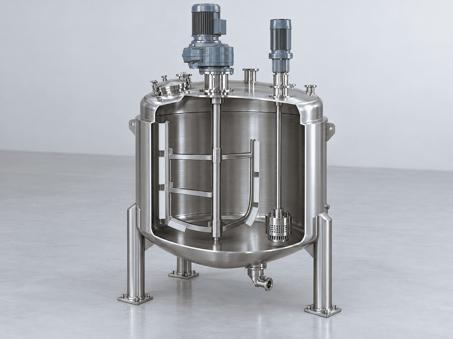
A drive above the vessel operates a rotor–stator head inside the batch. The homogenizer provides local high shear while the separate scraper agitator moves material through the vessel.
This arrangement suits an integrated vessel layout without an external homogenizing loop. The head must remain adequately immersed throughout the intended process. Check the lowest operating liquid level, shaft arrangement, lid access and clearance for lifting or maintenance.
Bottom-Mounted Internal Homogenizer

The homogenizing head is installed at the vessel bottom, with its drive and seal assembly below the product chamber. Bulk agitation must still bring material into the head's processing zone.
A low head position can help maintain immersion at lower fill levels, but it does not establish the machine's minimum batch size. Review the bottom profile, outlet arrangement, seal access and cleaning around the head. Reserve space below the vessel for service work.
External Recirculation Homogenizer

Product leaves the vessel, passes through an inline homogenizer and returns through a recirculation line. This separates the shear device from the main vessel and allows a defined external processing route.
The loop adds product hold-up, valves, seals and cleaning requirements. Flow depends on viscosity, pipe resistance and the homogenizer's pumping capability; some duties require a separate feed pump. Size the return connection and establish the required circulation or passes through process evaluation.
Scroll to view all columns.
| Selection point | Top-mounted internal | Bottom-mounted internal | External recirculation |
|---|---|---|---|
| Product route | High shear inside the vessel | High shear at the vessel bottom | High shear in an external loop |
| Minimum-batch check | Head immersion and bulk circulation | Bottom coverage and bulk circulation | Vessel level, loop hold-up and continuous feed |
| Maintenance space | Above the vessel and around the lid | Below and around the vessel base | Beside the vessel, around the inline unit and piping |
| Cleaning focus | Head, shaft, scraper and vessel | Bottom head, seal area and outlet | Vessel plus the complete product loop |
Match the Arrangement to the Process
Scroll to view all columns.
| Your process priority | Starting point for evaluation | Check before selecting |
|---|---|---|
| Keep the product route inside the vessel | Top-mounted internal homogenization with independent bulk agitation. | Head immersion at the smallest charge, circulation as viscosity rises, and overhead service access. |
| Process smaller charges within a production vessel | Evaluate a bottom-mounted head alongside the vessel geometry and agitator. | Continuous head coverage, representative temperature measurement, bulk circulation and access below the vessel. |
| Use a defined external processing route | External recirculation with a suitable feed and return arrangement. | Flow at processing viscosity, any feed-pump requirement, loop hold-up and cleaning of the complete circuit. |
| Protect a shear-sensitive gel or finished emulsion | Separate the high-shear stage from subsequent low-speed blending. | Ingredient order, temperature, shear exposure and whether the final structure tolerates further homogenization. |
These are selection starting points. Evaluate the product at its processing temperature and through cooling or thickening; a single viscosity reading or homogenizer location cannot determine the complete machine.
CAPACITY & TECHNICAL DATA
Capacity Options and Technical Specifications
Production capacity options include 50, 100, 200, 300, 500, 1,000 and 2,000 L. Laboratory options include 5, 10 and 20 L. Start with your normal batch and smallest planned batch, then select the vessel and drives together.
Illustrative Drive Schedule: Top-Mounted Internal Homogenizer
The following figures are preliminary configuration references for one top-mounted arrangement, not fixed ChannelVessel model ratings. Final motor selection, running speeds and vessel dimensions are specified for the quoted process. Bottom-mounted and external recirculation arrangements require their own sizing.
Scroll to view all columns.
| Reference working capacity (L) | Homogenizer motor (kW) | Scraper agitator motor (kW) | Homogenizer speed reference (rpm) | Scraper speed reference (rpm) |
|---|---|---|---|---|
| 50 | 4 | 1.5 | 0–3,600 | 0–50 |
| 100 | 4 | 1.5 | 0–3,600 | 0–50 |
| 200 | 4 | 1.5 | 0–3,600 | 0–50 |
| 300 | 5.5 | 2.2 | 0–3,600 | 0–50 |
| 500 | 7.5 | 3.7 | 0–3,600 | 0–50 |
| 1,000 | 15 | 5.5 | 0–3,600 | 0–50 |
| 2,000 | 18.5 | 7.5 | 0–3,600 | 0–50 |
Zero denotes stop; allowable continuous running speeds depend on the selected drive and load. Motor ratings in this table exclude electric heaters, the vacuum pump, phase-vessel drives and other auxiliaries. They do not represent total installed electrical load or energy consumed per batch.
Working Volume, Gross Volume and Minimum Batch
Working volume is the intended processing charge. Gross volume is the vessel's total internal volume, including space above that charge. Minimum batch is the lowest charge that maintains the required head immersion, circulation and temperature measurement under the specified process conditions.
A 500 L working-capacity vessel should not be treated as a 500 L gross-volume tank. Its usable minimum batch also cannot be assumed to be a fixed percentage of its maximum capacity. Foaming, vacuum operation, ingredient addition and changes in viscosity all affect the necessary operating space.
Laboratory results help define the process, but production scale-up must also consider circulation, heat transfer and the time spent under shear. Matching rpm alone does not establish equivalent processing.
Worked Planning Example: A 500 kg Cream Batch
The following example shows how batch requirements become equipment inputs. Every value below is an illustrative assumption, not a tested formulation, a completed customer project or a machine rating.
Assume a normal finished batch of 500 kg, a requested small batch of 250 kg, and a finished-product density of 1.00 kg/L at the specified processing condition. The corresponding charges are 500 L and 250 L. A 500 L working-capacity class is a starting point for the normal batch; the requested 250 L charge still needs immersion and circulation checks.
For phase preparation, assume 70% aqueous ingredients at 0.98 kg/L, 25% oil-phase ingredients at 0.90 kg/L, and 5% late additions, all percentages by mass. The densities are assumed inputs at the respective preparation conditions.
Scroll to view all columns.
| Planning item | Calculation | Result |
|---|---|---|
| Normal finished charge | 500 kg ÷ 1.00 kg/L | 500 L |
| Requested small charge | 250 kg ÷ 1.00 kg/L | 250 L; minimum-batch suitability remains to be established. |
| Aqueous phase | 500 kg × 70% = 350 kg; 350 ÷ 0.98 | Approximately 357.1 L before a filling allowance. |
| Oil phase | 500 kg × 25% = 125 kg; 125 ÷ 0.90 | Approximately 138.9 L before a filling allowance. |
| Late additions | 500 kg × 5% | 25 kg, already included in the finished batch mass. |
For arithmetic only, assume an 80% maximum filling fraction. Using gross volume ≥ charge volume ÷ 0.80 gives preliminary gross-volume allowances of at least 625 L for the main vessel, 447 L for the aqueous vessel and 174 L for the oil vessel, rounded upward where needed. The 80% assumption is not a universal operating limit or a rated fill level for the equipment.
Check the highest intermediate fill, foaming, vacuum expansion, addition sequence and agitator geometry before finalizing those allowances. Phase volumes at different preparation conditions should not be added to establish the finished-product volume. The drive schedule above remains a separate configuration reference; this volume calculation does not establish the required motor torque or prove a 250 L minimum operating batch.
SYSTEM PACKAGE & SUPPLY SCOPE
What the Complete Mixing System Includes
A main-vessel package includes the emulsifying vessel and its essential process equipment. A three-vessel arrangement adds separate oil and water phase preparation, allowing ingredients to be heated or premixed before transfer to the main vessel.

The proposed main-vessel package comprises:
- A jacketed emulsifying vessel with the selected cover, outlet and product connections.
- Independently controlled homogenizer and scraper agitator drives.
- A vacuum pump and associated vacuum-side connections suited to the duty.
- Temperature and vacuum indication, operating controls and agreed protective functions.
- A support structure and the valves and piping identified in the supply schedule.
Scroll to view all columns.
| Scope group | Equipment or interface | Supply treatment |
|---|---|---|
| Proposed main-vessel package | Main vessel, drives, vacuum equipment, instruments and control cabinet | Itemized in the equipment quotation, with materials, ratings and boundaries stated. |
| Phase preparation | Oil and water vessels, agitation, heating and transfer connections | Added for a three-vessel process; capacities follow the actual phase quantities. |
| Product handling | Feed or discharge pumps, recirculation piping, weighing, metering and automatic valves | Selected and priced according to the product and automation scope. |
| Cleaning and access | Spray devices, cleaning return piping, a CIP skid, platforms or stairs | Listed separately where required; a spray connection does not include a complete CIP system. |
| Factory facilities | Incoming power, steam generation, cooling-water supply, compressed air and site drains | Normally provided by the buyer unless expressly included. |
| Site work and services | Unloading, positioning, utility connection, commissioning or training | Responsibilities and service scope stated separately in the proposal. |
Evaluate quotations against the same equipment list, scope of supply and main vessel capacity.
For the 500 kg planning example, the proposal should address a 500 L normal finished charge, the requested 250 L small charge, and unequal oil and aqueous preparation quantities. Specify phase-vessel working and gross volumes separately, then identify the transfer route, heating and cooling interfaces, discharge equipment and control functions. A main-vessel price can only be compared with a three-vessel price after these scope differences are made explicit.
BATCH WORKFLOW & CONTROLS
Control the Batch from Phase Preparation to Discharge
The equipment supports a recipe-defined process. Addition order, vacuum timing, shear exposure and cooling stages should follow your formulation and development results.
- Prepare the phases. Heat, dissolve or premix ingredients in the main vessel or separate phase vessels, using agitation suited to each material.
- Transfer and add ingredients. Use the specified vacuum-assisted transfer, pumping or metered addition arrangement. Account for liquid level, powder wetting and the rate of addition.
- Homogenize and circulate. Operate the rotor–stator head and scraper independently to provide the required shear and bulk movement.
- Cool and deaerate. Adjust jacket cooling, agitation and vacuum as viscosity changes. Add sensitive ingredients at the temperature and shear conditions established for the recipe.
- Discharge and clean. Transfer the finished batch through the selected outlet or pump, then follow the cleaning procedure for the vessel, seals and connected piping.
Scroll to view all columns.
| Control point | Operating purpose | Configuration choices |
|---|---|---|
| Product temperature | Manage heating, cooling and addition stages | Temperature indication and control; specified jacket valves and heating controls. |
| Agitator and homogenizer speeds | Adjust bulk movement and shear independently | Separate drive controls and, where selected, variable-frequency drives. |
| Vacuum | Manage deaeration or vacuum-assisted transfer | Vacuum indication with manual or automated control components. |
| Stage time and ingredient addition | Follow the established processing sequence | Operator-led steps or optional PLC/HMI sequencing and metering. |
| Batch records | Record selected process values and operating events | Optional logging, recipe storage and data export, with the required functions defined. |
Push-button controls suit operator-led production. PLC/HMI control can add recipe handling, sequencing and records; these functions are selected individually and depend on the installed instruments and actuators.
MATERIALS & CLEANING ACCESS
Product-Contact Design and Cleaning Access
An available material arrangement uses SS316L for product-contact parts and SS304 for non-contact outer cladding. Specify the contact-material boundary across the vessel, homogenizer, valves, piping and transfer equipment. Seal elastomers and scraper materials must suit the formulation, operating temperature and cleaning chemicals; PTFE scrapers are one available option.
For the vessel material and fabrication choices behind this arrangement, see our stainless steel mixing tanks. The material selection should cover every wetted component and the intended cleaning procedure.

Surfaces, Drainage and Access
Define the required weld treatment, surface finish and inspection method alongside the vessel design. Review drainage from the vessel and connected piping, access around the homogenizer, and how operators will inspect seals and remove components for maintenance.
A lifting cover improves access to the vessel interior but needs overhead clearance and appropriate operating protection. A fixed cover changes the access arrangement and should be assessed against cleaning and maintenance tasks.
Define the Cleaning System Boundary
A spray ball or CIP connection provides an interface for cleaning liquid. A complete cleaning circuit also needs suitable supply and return paths, flow, temperature, chemistry and drainage. A CIP skid adds the equipment needed to prepare and circulate those cleaning solutions within its specified scope.
Cleaning coverage and residue acceptance must be established for the actual product and procedure. SS316L construction and a closed vessel do not, by themselves, establish sterile operation or validated cleaning.
FACTORY SERVICES & INSTALLATION
Utilities, Footprint and Installation Requirements
Plan the equipment together with the factory services. Heating method, cooling duty, vacuum equipment and auxiliary vessels can change both the installed load and the space required.
Scroll to view all columns.
| Factory interface | Information used for equipment selection |
|---|---|
| Electrical supply | Voltage, frequency, phase and available capacity. Options include 220, 380 and 480 V three-phase arrangements, with 50 or 60 Hz components selected for the destination. |
| Heating | Electric jacket heating or a steam-heated jacket; required product temperatures, heating time and available thermal supply. |
| Cooling | Available water or chilled-water temperature, flow and pressure, plus the required product cooling profile. |
| Vacuum support | Selected pump type, vapour or condensate handling, and any associated cooling or service-water connections. |
| Compressed air | Available pressure and quality where pneumatic valves or other selected components require air. |
| Cleaning and drainage | Cleaning-liquid supply, return arrangements, drain locations and the boundary of any supplied CIP equipment. |
The electrical schedule must cover the complete selected package, including heaters and auxiliaries. Final utility duties follow the batch mass, product properties, temperature change and required processing time.

Heat-Duty Check for the Planning Example
For a simplified sensible-heat balance, assume the 500 kg batch has an average specific heat capacity of 3.5 kJ/(kg·K) and is heated from 25°C to 75°C.
Q = mass × specific heat capacity × temperature rise Q = 500 × 3.5 × (75 − 25) = 87,500 kJ ≈ 24.3 kWh.
Delivering that sensible heat in one hour would require approximately 24.3 kW of average net heat input to the product. This is an illustrative heat balance, not a heater rating or a promised heating time. Final sizing must include vessel heating, heat losses, any melting or evaporation, changing properties, jacket heat transfer and the available utility temperatures. Where phases are preheated separately, allocate their duties across the phase vessels and main vessel without counting the same heat twice.
Our jacketed mixing tanks page explains the vessel-side heating and cooling choices. For an emulsifying package, specify the complete thermal circuit and its supply boundary as well.
The layout drawing should show the operating footprint, fully raised cover height where applicable, maintenance access, phase vessels, control cabinet and transfer routes. Include access through doors and the installation route when planning delivery.
For pressure and vacuum specifications, identify the main vessel and jacket separately. State whether values are gauge or absolute, and distinguish process settings from design limits. Vacuum capability does not automatically permit positive-pressure operation or pressure-assisted discharge.
CONFIGURATION & EQUIPMENT BUDGET
Customization Options and What Affects the Price
Systems with the same working capacity may differ in cost if they perform different duties or include different equipment. Review the proposed configuration, automation and scope of delivery before evaluating price.
Illustrative 100 L Equipment Budget
For preliminary budgeting, a separate 100 L working-capacity arrangement with a bottom-mounted homogenizer can be illustrated as follows. The reference basis is FOB Shanghai, reviewed in October 2026. These are budget references, not ChannelVessel selling prices or a formal quotation.
Scroll to view all columns.
| Budget item | Illustrative amount (USD) |
|---|---|
| 100 L main emulsifying unit | Approximately $11,000 |
| Oil and water phase-vessel option | Approximately $4,000 |
| Equipment subtotal for these two lines | Approximately $15,000 |
This illustration is separate from the top-mounted drive schedule and the 500 kg planning example. It does not establish a fixed package, the exact automation level, all accessories or a complete delivered-project cost. Freight, insurance, import charges, site work, commissioning and any additional transfer or CIP equipment need explicit quotation lines; no amounts for them are included in this illustration.
The price depends on the required materials, surface requirements, inspection documents, packing, transport and agreed site services. Some options require changes elsewhere in the system, so assess the arrangement as a whole.
MANUFACTURING & PROJECT RECORDS
Manufacturing Checks and Factory Acceptance
ChannelVessel is the brand used by Guangdong Chengliu Intelligent Equipment Co., Ltd. for overseas industrial process equipment projects. See our company and manufacturing background when reviewing the supplier and the proposed project responsibilities.
Agree on the inspection and acceptance plan before fabrication. It should state what will be checked, how results will be documented and which acceptance criteria apply to the selected equipment package.

Scroll to view all columns.
| Check area | Items to include in the agreed plan |
|---|---|
| Drawings and supply scope | Vessel arrangement, capacities, drives, connections, controls and equipment boundaries. |
| Materials | Specified product-contact materials and the agreed level of material identification and traceability. |
| Fabrication and finish | Weld condition, specified surface treatment, accessible areas and drainage arrangements. |
| Vacuum and leakage | Test method, test conditions, instruments and acceptance criteria for the relevant vessel and connections. |
| Drives and protective functions | Rotation, selected speed controls, emergency stops and the interlocks included in the design. |
| Thermal operation | Heating and cooling functions under the agreed test conditions and available utilities. |
| Product trial, if included | Representative formulation, batch size, processing conditions, sampling method and measurable acceptance targets. |
| Delivery documentation | Approved drawings, component information, operating and maintenance instructions, and agreed inspection records. |
A water run can check selected mechanical and control functions. It does not establish cream viscosity, emulsion droplet size or production cycle time. Where a product trial is included, record the formulation, batch quantity, temperatures, speed settings, vacuum conditions and processing time. Define how results such as viscosity or droplet size will be measured, then compare actual results with the agreed targets.
Connect Each Claim to a Project Document
Define the documentation scope in the purchase order so the equipment can be checked against an agreed record.
Scroll to view all columns.
| Project record | What it should identify |
|---|---|
| Equipment schedule | Item identifiers, working and gross volumes, required batch range, materials, drives, heaters and utility interfaces. |
| General arrangement and connection schedule | Operating and raised-cover dimensions, service access, vessel positions and connection locations. |
| Product-contact material schedule | The wetted boundary, material grades, seals and scrapers, plus the agreed traceability documents. |
| Factory test record | Equipment identity, test method, instruments, conditions, acceptance criteria and actual results for the checks included. |
| Product-trial record, if included | Formulation identification, charge, process settings, sampling and measurement methods, target values and actual results. |
| Handover information | Operating and cleaning instructions, maintenance access, component details and the agreed spare-parts information. |
A drawing or proposed inspection plan defines what is to be supplied or checked. An actual inspection or trial record must identify the equipment, conditions and results of that test. Agree which documents are provided before fabrication approval, at factory acceptance and with delivery.
COMMON BUYER QUESTIONS
Vacuum Emulsifying Mixer FAQs
What limits the minimum batch size?
The homogenizing head must stay adequately immersed, the agitator must circulate the charge, and temperature probes must remain in a representative product zone. Vessel geometry, foaming and changes in viscosity also matter. An external loop adds product hold-up and a continuous-feed requirement. Establish the minimum usable batch for the selected arrangement rather than applying a fixed percentage to vessel capacity.
Can one system handle both hot and cold processes?
Yes, a suitably configured system can support both. Hot processing requires an appropriate heating arrangement and a controlled cooling stage. Cold processing may still require jacket cooling to manage heat generated during mixing. Check the recipe temperatures, seal compatibility and available utilities. The processing sequence and shear exposure can differ between formulations.
Can I switch between creams, lotions and gels?
A system may handle several formulations when its torque, circulation, usable batch range and materials suit each one. Check the most demanding product at its actual processing temperature, including changes during cooling or thickening. Some gels require limited shear after structure develops. Product changeovers also need suitable drainage, cleaning access and a procedure that addresses residues from the previous batch.
Is vacuum always required during homogenization?
No. Vacuum is a process tool for deaeration or selected transfer steps, and its timing should follow the recipe. Some stages can operate without it; others may benefit from controlled vacuum. Select the level and timing around foaming, volatile ingredients, temperature and circulation. The equipment's vacuum design limits remain separate from the settings used for a particular batch.
How are oil and water phase tanks sized?
Use the largest actual quantity of each phase, its volume at preparation temperature, the required mixing space and any allowance for foaming or addition. The two vessels do not need to be equal, and a fixed oil-to-water tank ratio will not suit every recipe. Preparation time and transfer timing also matter when phase vessels serve repeated production batches.
Does a CIP spray ball include a complete cleaning system?
No. A spray ball distributes cleaning liquid supplied to it. A complete system also needs the specified cleaning solution, supply flow, temperature, circulation equipment, return path and drainage. If a CIP skid is required, its tanks, pumps, heating and controls must be included in the quotation. Cleaning performance still depends on the installed circuit and the product-specific procedure.
Can the system match a 60 Hz factory power supply?
Yes, a 60 Hz configuration can be specified with the appropriate voltage and phase. The selection must cover the main drives, vacuum pump, phase-vessel motors, heaters and control components. Provide the factory supply details and any applicable electrical requirements so the complete equipment package can be matched to the destination.
What determines the final machine price?
Working capacity is one factor. Homogenizer arrangement, motor sizing, materials, heating method, phase vessels, automation, transfer equipment and cleaning scope also contribute. Inspection requirements, documentation, packing, transport and site services affect the delivered project cost. A useful quotation lists each included item and clearly identifies the factory facilities or services outside the equipment supply.
START YOUR EQUIPMENT DISCUSSION
Discuss Your Product and Batch Requirements
Provide your process brief, details of your current equipment or a layout drawing. ChannelVessel can use these inputs to propose a vacuum emulsifying mixer configuration and an itemized equipment scope.
- Product and properties: formulation type, density, viscosity with measurement temperature, solids and ingredients that affect materials or seals.
- Batch range: normal production quantity, smallest planned batch and whether quantities are stated in litres or kilograms.
- Process and quality targets: heating and cooling stages, addition sequence, shear-sensitive ingredients and the required test methods or acceptance targets.
- Factory services: voltage, frequency, phase, heating supply, cooling water and compressed air where required.
- Layout and delivery: available floor space, overhead clearance, transfer connections, destination and required supply or service scope.